Vehicle cooling system

A cooling system and vehicle technology, which is applied in engine cooling, coolant flow control, engine components, etc., can solve the problems of large flow energy consumption loss, inability to distribute according to demand, and inability to achieve large flow, etc., to achieve flexible control, The effect of avoiding energy loss

Active Publication Date: 2017-09-15
ANHUI JIANGHUAI AUTOMOBILE GRP CORP LTD
View PDF10 Cites 4 Cited by
  • Summary
  • Abstract
  • Description
  • Claims
  • Application Information

AI Technical Summary

Problems solved by technology

[0003] Once the design is frozen, under the same working condition, the flow distribution of each branch is fixed and cannot be distributed according to demand. The increase or decrease of the flow of each branch is mainly controlled by the speed of the pump at the same time, and the relationship with the temperature is only It is adjusted by the change of the speed of the water pump. The low speed of the water pump cannot achieve large flow, and the high speed will generate redundant large flow and cause energy loss.

Method used


Image

  • Vehicle cooling system
  • Vehicle cooling system
  • Vehicle cooling system

Examples


Embodiment 1

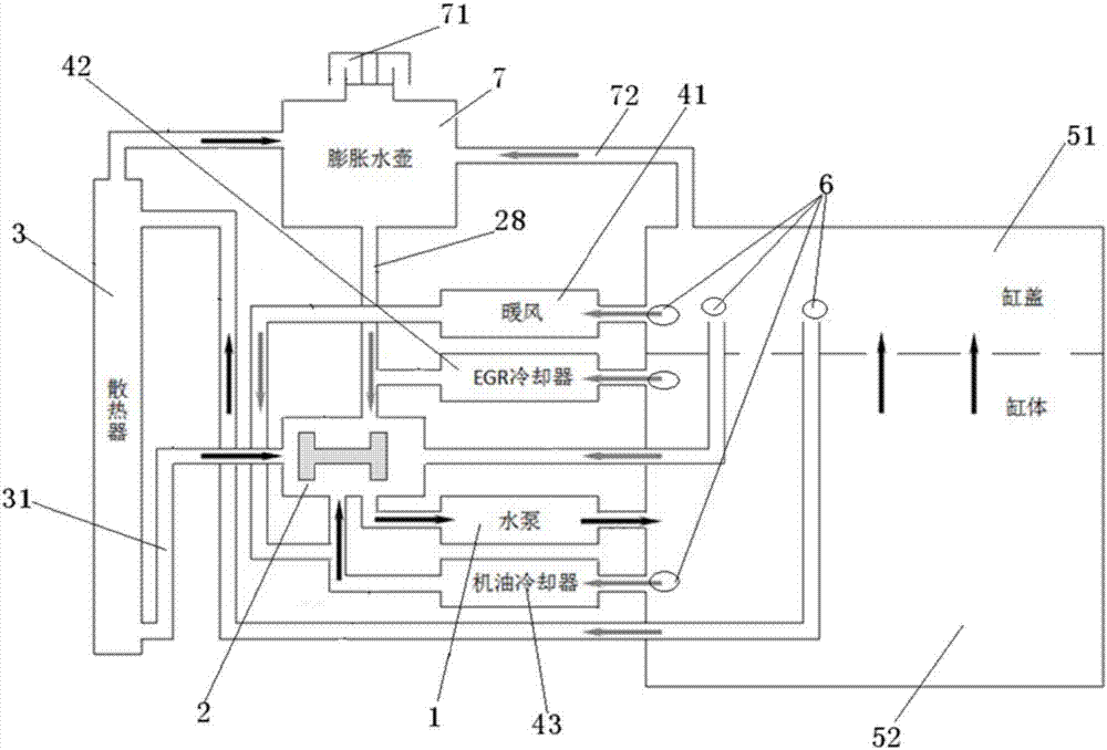
[0032] Such as figure 1 shown, see also figure 2 , the present invention provides a vehicle cooling system according to an embodiment. The vehicle cooling system includes a radiator 3, a cylinder body 52, a cylinder head 51, a flow control structure 2, a warm air return pipeline 41, and an oil cooler return pipeline 43 , the cooler return water pipeline 42 and the water pump 1, the flow control structure 2 includes a water temperature sensor 6, a control structure and a main valve structure,

[0033] The cylinder head 51 is connected to the water inlet of the warm air return pipeline 41, the cylinder head 51 is also connected to the water inlet of the radiator 3 through the water inlet pipeline, and the cylinder body 52 is respectively connected to the oil cooler return water pipeline The water inlet of 43 and the water inlet of the cooler return water pipeline 42 are connected, and the main valve structure is arranged between the water outlet pipeline 31 of the radiator 3 a...

Embodiment 2

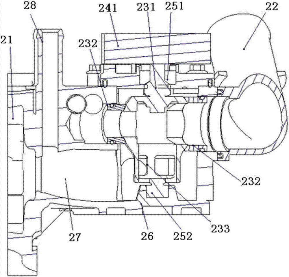
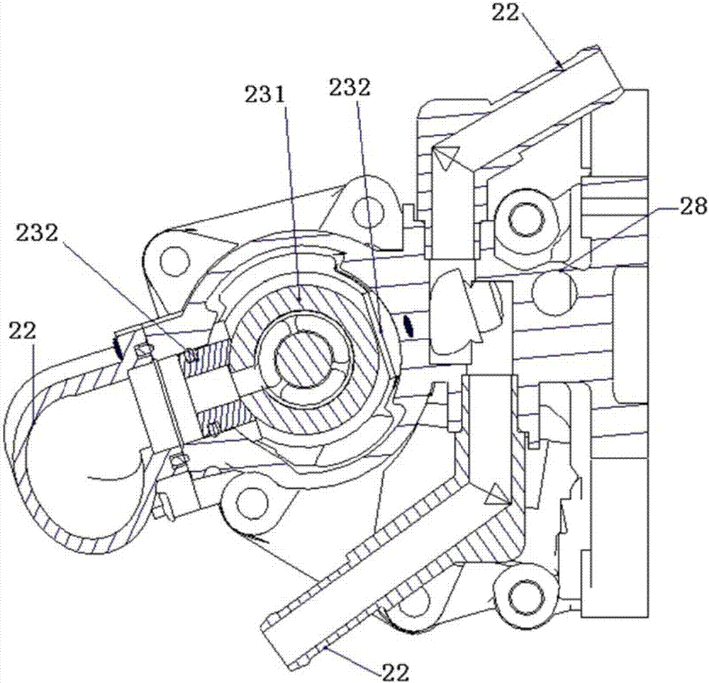
[0044] The embodiment of the present invention describes the specific situation of the flow control structure, such as figure 2 shown, see also image 3 , the embodiment of the present invention provides a flow control structure applied to the vehicle cooling system, the flow control structure includes: a water temperature sensor 6, a control structure and a main valve structure, and each water flow branch 22 is provided with the water temperature sensor 6. The main valve structure is arranged at the water outlet of each water flow branch 22, and the water temperature sensor 6 is sequentially connected with the control structure and the main valve structure;

[0045] When working, the water temperature sensor 6 sends the water temperature signal of the water flow branch 22 to the control structure, and the control structure controls the main valve structure to open or close the water flow branch 22; when the main valve structure opens any water flow When the branch 22 is use...

Embodiment 3

[0061] The embodiment of the present invention describes in detail the specific conditions of the water pump: as Figure 4 shown, see also Figure 5, the present invention provides a clutch type electric control water pump, the clutch type electric control water pump includes a water pump body, a clutch structure, and the clutch structure includes a driving mechanism 12, a clutch shoe 13, a clutch disc 14 and a one-way bearing 16, The driving mechanism 12 is arranged on the casing 11 of the water pump body, and the driving mechanism 12 is connected with the clutch shoe 13, the driving mechanism 12 is used to drive the clutch shoe 13 to move, the The clutch disc 14 is connected with the bearing 15 of the water pump body, the one-way bearing 16 is arranged between the bearing 15 of the water pump body and the pulley 17, and the inner ring 161 of the one-way bearing 16 is connected with the water pump body The bearing 15 is connected, and the outer ring 162 of the one-way bearin...


PUM


Abstract

The invention discloses a vehicle cooling system which comprises a radiator, a cylinder body, a cylinder cover, a flow control structure, a heater water return pipeline, an oil cooler water return pipeline, a cooler water return pipeline and a water pump. The flow control structure comprises a water temperature sensor, a control structure body and a main valve structure. According to the vehicle cooling system, the water temperature sensor sends water temperature signals of the heater water return pipeline, the oil cooler water return pipeline, the cooler water return pipeline and a water inlet pipeline of the radiator to the control structure body in time, and according to the water temperature signals, the control structure body flexibly controls the main valve structure to open or close all the pipelines, so that the situation that water flow branch flows in all the pipelines are flexibly controlled is realized, overall on-demand deployment is realized, and unnecessary energy consumption losses are avoided.

Description

technical field [0001] The invention relates to the technical field of vehicle cooling, in particular to a vehicle cooling system. Background technique [0002] The distribution of the traditional cooling system is realized by fixed structural pipelines. In related systems, a double-valve thermostat is generally used to control the large cycle (connected to the radiator branch) and the small cycle (water pump-cylinder block-cylinder head-water pump). The oil cooler, exhaust gas recirculation (EGR) cooler, and front and rear heating air branches are all in a normally open state. Usually, the internal pipe diameter of each branch is designed based on the results of fluid analysis. [0003] Once the design is frozen, under the same working condition, the flow distribution of each branch is fixed and cannot be distributed according to demand. The increase or decrease of the flow of each branch is mainly controlled by the speed of the pump at the same time, and the relationship w...

Claims


Application Information

Patent Timeline
Patent Type & Authority Applications(China)
IPC IPC(8): F01P7/16F01P7/14
Inventor 陈晓东胡必谦高巧陆荣荣肖海云代兴伟喻昆许涛李昌冶金鑫吴鹏杨洪震张波
Owner ANHUI JIANGHUAI AUTOMOBILE GRP CORP LTD
Why Eureka
Try Eureka