Fluid dispenser

a dispenser and flue gas technology, applied in the field of flue gas dispensers, can solve the problems of inadaptation of the device shape and the ergonomics, and achieve the effect of great accuracy

Active Publication Date: 2013-08-22
APTAR FRANCE SAS
View PDF8 Cites 20 Cited by
  • Summary
  • Abstract
  • Description
  • Claims
  • Application Information

AI Technical Summary

Benefits of technology

[0006]This type of light is already used in institutes for combating inflammation, boosting collagen synthesis, improving vascularization, accelerating the repair of stretch marks or scar tissue, and also for reducing pain. Thus, it is already known to subject the skin to radiation that is pure in color or “monochromatic”, in the range blue to red. However, it is especially the red and the near infrared that provide such performance. Infrared light is thermal radiation at a wavelength of about 700 nm or longer. The light heats the area being treated, stimulates blood circulation, heats tissues, and activates fibroblasts. With regard to red light, it mainly stimulates metabolisms for regenerating the skin by producing new collagen: this is referred to as collagen neosynthesis. In order to generate such light, it is possible to use LEDs or low power lasers in low level laser therapy (LLT).
[0017]The dispenser of the invention mat thus be easily handled as a pen by a user for a personal application, namely at the face.
[0019]According to another advantageous characteristic, the source of radiation may emit light from the application wall. Preferably, the source of radiation emits light through the application wall. Advantageously, at least locally, the application wall is made out of a material that is transparent and / or translucent to the light emitted by the source of radiation, the source emitting light through said material towards the skin. Preferably, the application wall guides or conveys the light emitted by the source of radiation. Thus, the application wall performs two functions, namely a first function of transmitting / guiding the light coming from the source of radiation, and a more conventional second function of applying / spreading the dispensed fluid. The fact of using the application wall to guide or convey the light is a characteristic that is particularly advantageous. Another advantage that is inherent to this embodiment resides in the fact that the distance between the light source and the skin is constant and unvarying, since it is determined by the application wall that is itself at a determined and unvarying distance relative to the light source. It is thus possible to determine, with accuracy, the length of time during which the skin is irradiated or illuminated, as a function of the power of the emitted light, of the distance between the light source and the application wall, and of the diffusing qualities and characteristics of the application wall. Thus, it suffices for the user to be exposed to the light only once in order to guarantee the desired effect. In addition, because the light is emitted through the application wall, this necessarily implies that the fluid is separated from the light source by the application wall, such that the light source cannot be soiled with fluid in any way.
[0023]In another advantageous aspect of the invention, the actuator member is movable in an actuation direction that is substantially perpendicular to a direction for dispensing the fluid through the dispenser orifice. Thus, the dispenser may be taken hold of and used like a pen, pressing laterally on the actuator member by means of the index finger, which makes it possible to hold the dispenser with great accuracy.
[0026]The spirit of the invention resides in the fact of incorporating, in a single dispenser, one or more sources of radiation capable of treating the skin, and an applicator capable of spreading a fluid on the skin. The compact configuration and the ergonomic shape, comparable to a pen, allow an easy utilization.

Problems solved by technology

The ergonomics and shape of the devices are not adapted to an individual utilization for cosmetics application.

Method used


Image

  • Fluid dispenser
  • Fluid dispenser
  • Fluid dispenser

Examples


Embodiment Construction

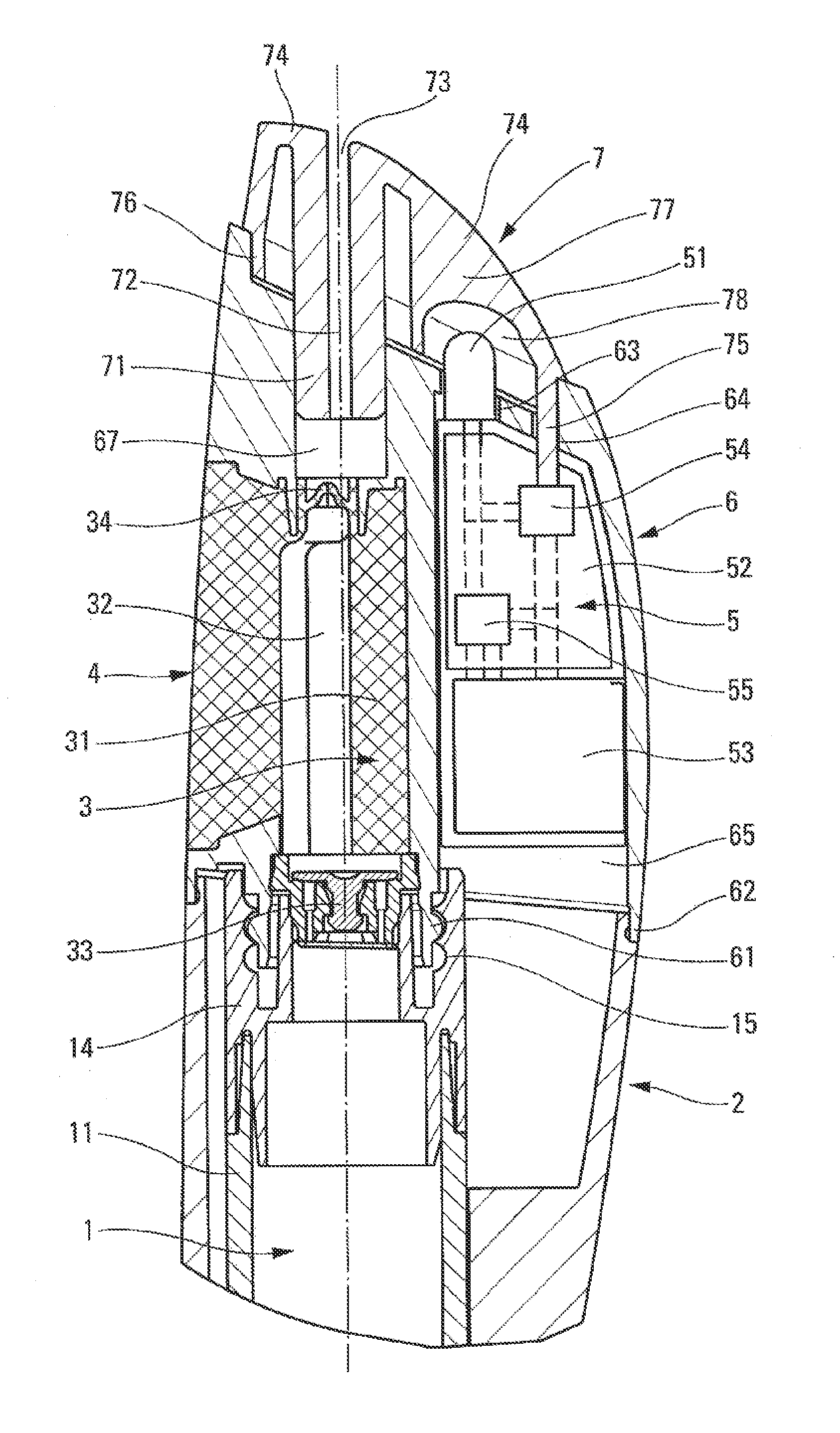
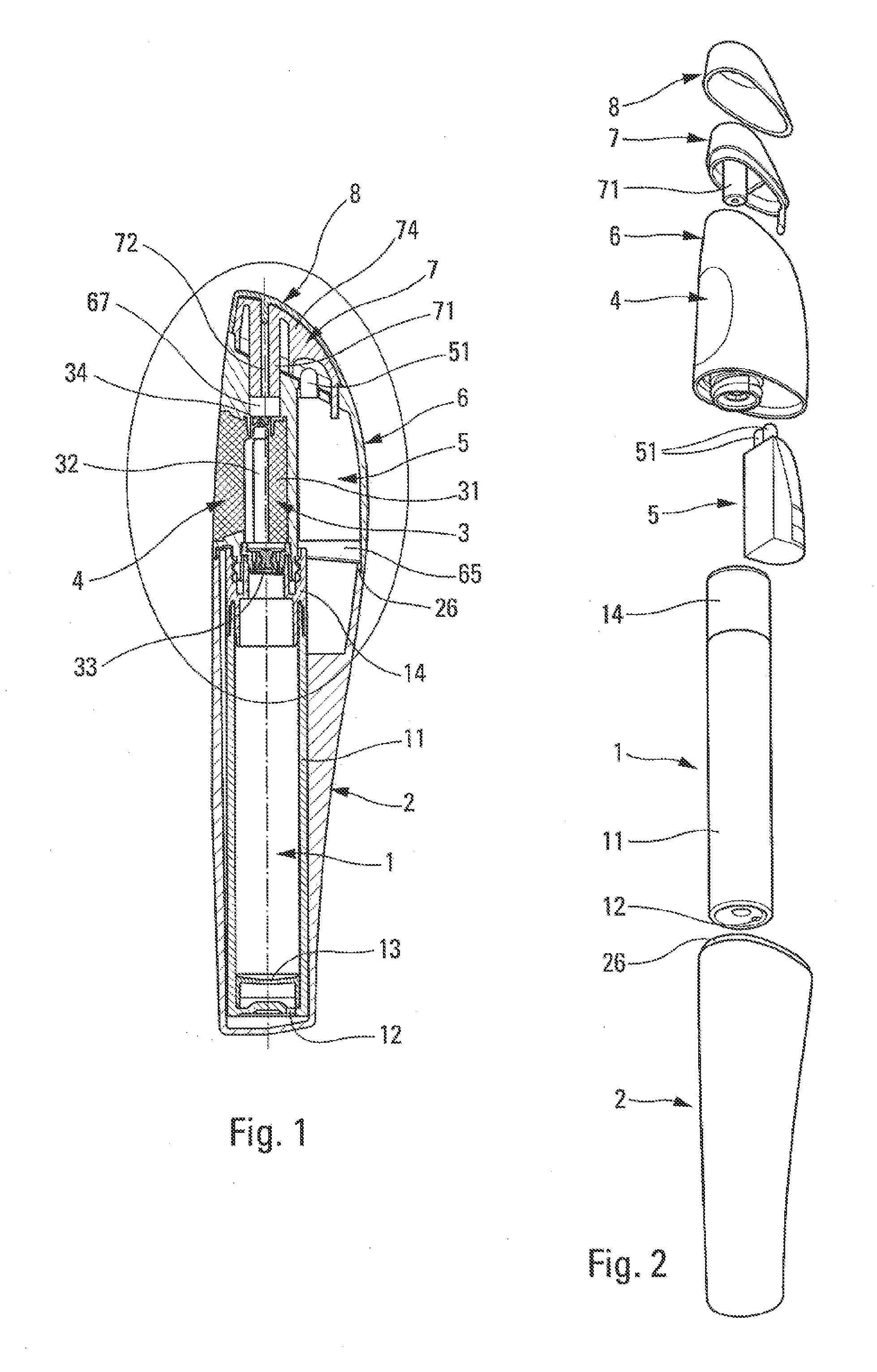
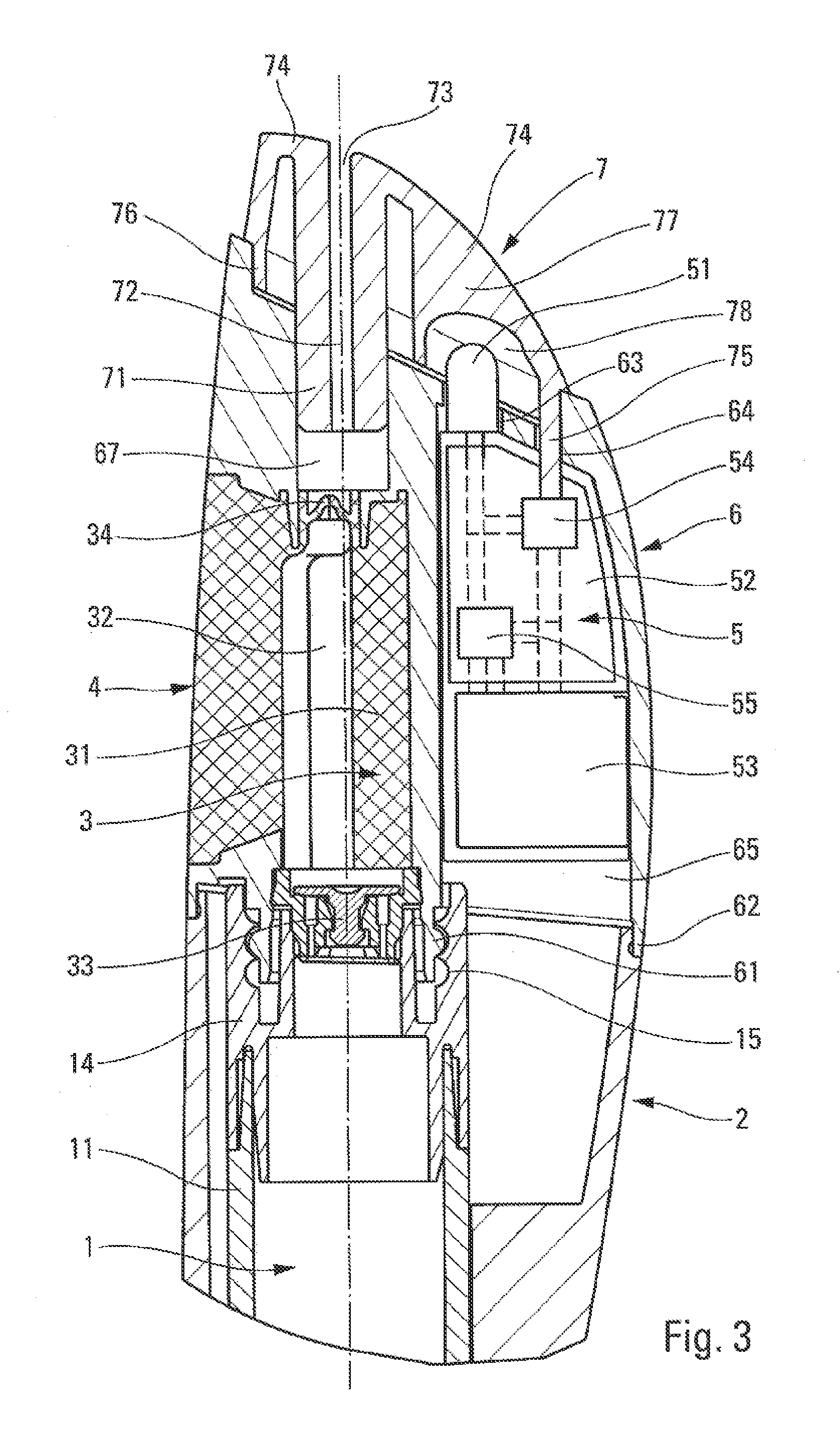
[0033]Reference is made to FIGS. 1 to 3 taken together in order to describe in detail the structure and the operation of a dispenser in a non-limiting embodiment of the invention.

[0034]The dispenser comprises: a fluid reservoir 1; a casing 2 in which the reservoir 1 is received; a dispenser member 3, specifically a pump; an actuator member 4 for actuating the pump 3, and that is specifically incorporated in the pump; a module 5 that is provided with one (or more) sources of radiation 51; a body 6 that receives the pump 3, the actuator member 4, and the module 5; and finally a dispenser head 7 that is mounted on the body 6. Optionally, the dispenser may also include a protective cap 8 that covers the dispenser head 7. With the exception of the module 5, all of the component elements of the dispenser may be made by injection-molding plastics material. The dispenser is shown approximately life-size in FIG. 1. It should be observed that the dispenser is not circularly symmetrical, but g...


PUM


Abstract

A fluid dispenser comprising:a fluid reservoir (1); anda body (6) receiving:a dispenser member (3) that is connected to the reservoir (1);an actuator member (4) for actuating the dispenser member (3);a dispenser and diffuser head (7) forming a fluid dispenser orifice (73) and an application wall (74) for applying the fluid coming from the dispenser orifice (73) onto the skin;a module (5) comprising at least one source of radiation (51), such as an LED, each emitting monochromatic light of 400 nm to 700 nm, and having an anti-inflammatory action and / or a stimulating action for stimulating skin-regeneration metabolisms;characterized in that the dispenser and diffuser head (7) comprises a source housing (78), and in that the body (6) comprises a module housing (65) wherein the module (5) is received, this module housing (65) communicating with the source housing (78) so that the source of radiation (51) extends in the source housing (78) of the head (7).

Description

CROSS REFERENCE TO RELATED APPLICATION[0001]This application claims the benefit under 35 U.S.C. §119(e) of pending U.S. provisional patent application Ser. No. 61 / 613,632, filed Mar. 21, 2012, and priority under 35 U.S.C. §119(a)-(d) of French patent application No. FR-12 51482, filed Feb. 17, 2012.TECHNICAL FIELD[0002]The present invention relates to a fluid dispenser comprising: a fluid reservoir; a fluid dispenser member that is connected to the reservoir; an actuator member for actuating the dispenser member; a fluid dispenser orifice that is connected to the dispenser member; and an application wall for applying the fluid coming from the dispenser orifice onto the skin. This dispenser, which can also be described as an applicator, finds an advantageous application in the fields of cosmetics and pharmacy, and more generally in the field of treating and caring for the skin.BACKGROUND OF THE INVENTION[0003]In the prior art, numerous dispensers already exist that are capable of dis...

Claims


Application Information

Patent Timeline
Patent Type & Authority Applications(United States)
IPC IPC(8): A61N5/06
CPCA61N5/0616A45D2200/205A61B2019/465A61N2005/0644A61N2005/0651A61N2005/0652A61N2005/0663A61N2005/0668A61N2005/063A61N2005/0662A61N2005/0626A61M35/00B05B11/0037B05B11/0048B05B11/3032A45D34/04A45D2200/055A45D2200/056A61N5/062A61B2090/065B05B11/0038B05B11/028B05B11/1032
Inventor DUQUET, FREDERICMARTINS-REIS, SANDRAMOREAU, FRANCISROULLET, FLORENCE
Owner APTAR FRANCE SAS
Why Eureka
Try Eureka