Apparatus and method for processing sensor data in sensor network

Active Publication Date: 2013-08-22
HYUNDAI MOTOR CO LTD +1
4 Cites 10 Cited by

AI-Extracted Technical Summary

Problems solved by technology

A service providing situation recognition information through such machine learning can provide good situation recognition performance as a dimension of a feature vector is high, but there is a problem that a system memory request amount and a calculation amount of a high dimensional feature vector increase.
Particularly, when situation recognition information is provided through cooperation of various sensors, there i...

Method used

[0085]Further, by forming situation information determination reference sensor data in a feature vector identifier table and by comparing situ...

Benefits of technology

[0008]The present invention has been made in an effort to provide a method and apparatus for processing sensor data in a sensor network that can solve a problem of a calculation amount of a high dimensional f...

Abstract

In a sensor network, a sensor data processing apparatus generates a feature vector identifier table by classifying feature vector identifiers of a plurality of situation information determination reference data to be a reference of situation determination according to a sensor type index and a feature vector identifier set index of the plurality of situation information reference data. When the sensor data processing apparatus receives sensor data, the sensor data processing apparatus generates a feature vector identifier of the sensor data and extracts a sensor type index and a feature vector identifier set index of a feature vector identifier most similar to the feature vector identifier of sensor data with reference to a feature vector identifier table, and generates situation recognition information using the extracted sensor type index and feature vector identifier set index.

Application Domain

Digital computer detailsData switching by path configuration +2

Technology Topic

Machine learningData processing +3

Image

  • Apparatus and method for processing sensor data in sensor network
  • Apparatus and method for processing sensor data in sensor network
  • Apparatus and method for processing sensor data in sensor network

Examples

  • Experimental program(1)

Example

[0028]In the following detailed description, only certain exemplary embodiments of the present invention have been shown and described, simply by way of illustration. As those skilled in the art would realize, the described embodiments may be modified in various different ways, all without departing from the spirit or scope of the present invention. Accordingly, the drawings and description are to be regarded as illustrative in nature and not restrictive. Like reference numerals designate like elements throughout the specification.
[0029]In addition, in the entire specification and claims, unless explicitly described to the contrary, the word “comprise” and variations such as “comprises” or “comprising” will be understood to imply the inclusion of stated elements but not the exclusion of any other elements.
[0030]Hereinafter, a method and apparatus for processing sensor data in a sensor network according to an exemplary embodiment of the present invention will be described in detail with reference to the drawings.
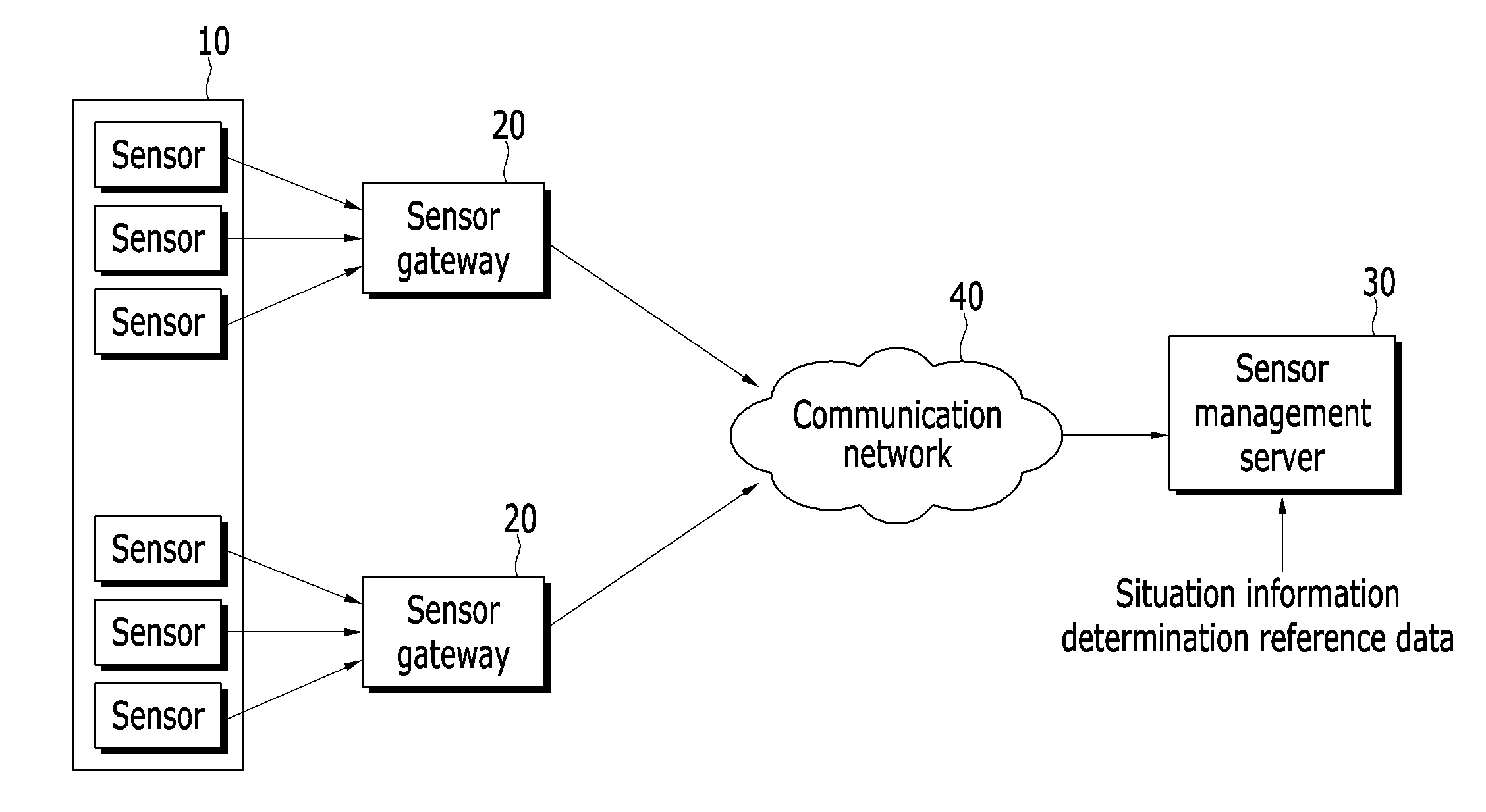
[0031]FIG. 1 is a diagram illustrating a sensor network system according to an exemplary embodiment of the present invention.
[0032]Referring to FIG. 1, the sensor network system includes a sensor 10, a sensor gateway 20, and a sensor management server 30.
[0033]The sensor 10 detects physical data such as light, sound, temperature, and motion in a physical space, and transfers the detected data to the sensor gateway 20. Hereinafter, data that is detected by the sensor 10 is referred to as sensor data.
[0034]The sensor network system collects necessary data using various kinds of sensors 10, and the sensor data may include recognition information of an object and peripheral environment information (temperature, humidity, illumination, contamination information, crack information, etc.) according to a kind of the sensor 10.
[0035]The sensor gateway 20 acquires sensor data from the sensor 10, processes the acquired sensor data, and transmits the processed sensor data to the sensor management server 30 through a communication network 40.
[0036]The sensor management server 30 manages the sensor gateway 20 and processes a plurality of reference data to be a reference for situation determination.
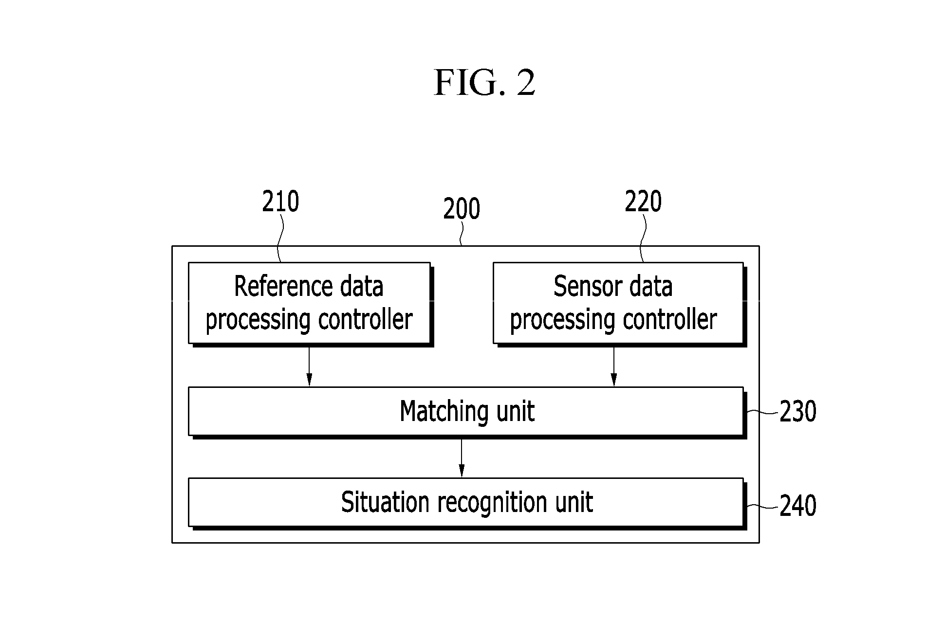
[0037]FIG. 2 is a block diagram illustrating a configuration of a sensor data processing apparatus of a sensor network system according to an exemplary embodiment of the present invention, FIG. 3 is a block diagram illustrating a configuration of a reference data processing controller that is shown in FIG. 2, and FIG. 4 is a block diagram illustrating a configuration of a sensor data processing controller that is shown in FIG. 2.
[0038]Referring to FIG. 2, a sensor data processing apparatus 200 includes a reference data processing controller 210, a sensor data processing controller 220, a matching unit 230, and a situation recognition unit 240.
[0039]In order to determine situation recognition information, the reference data processing controller 210 previously analyzes sensor data and generates a feature vector identifier from defined data. Hereinafter, data that is defined by previously analyzing sensor data in order to determine situation recognition information is referred to as situation information determination reference data. The sensor data processing controller 220 generates a feature vector identifier from data that are sensed from a plurality of sensors 10.
[0040]Referring to FIG. 3, the reference data processing controller 210 includes a pretreatment unit 211, an extractor 212, a table generator 213, and a table storage unit 214.
[0041]The pretreatment unit 211 performs pretreatment that removes noise of situation information determination reference data. The pretreatment unit 211 removes noise from reference data through a signal processing technique such as a band-limited filter, a high-limited filter, and a low pass filter.
[0042]The extractor 212 analyzes a characteristic pattern of pretreated situation information determination reference data, and summarizes feature vectors that can abstract a characteristic pattern with a fixed bit series having a fixed length of two dimensions, thereby generating a feature vector identifier of reference data. That is, a fixed bit series of an N×M form may become a feature vector identifier of situation information determination reference data that is defined by a user. The extractor 212 expresses a feature vector of reference data with a fixed bit series through time series analysis or frequency analysis.
[0043]The table generator 213 classifies feature vector identifiers of situation information determination reference data into a feature vector identifier set index group according to situation information that is defined by the user and groups a feature vector identifier set index into a sensor type index, thereby generating a feature vector identifier table.
[0044]That is, the feature vector identifier is stored to a feature vector identifier table together with the sensor type index and a feature vector identifier set index. The sensor type index is determined according to a sensor type of reference data, and the feature vector identifier set index is determined by the user according to situation information of the same type.
[0045]The table storage unit 214 stores a feature vector identifier table.
[0046]Further, referring to FIG. 4, the sensor data processing controller 220 includes a pretreatment unit 221, an extractor 222, and a storage unit 223.
[0047]The pretreatment unit 221 removes noise from sensor data that is presently collected from the sensor 10 through pretreatment. The pretreatment unit 221 removes noise from sensor data through a signal processing technique such as a band-limited filter, a high-limited filter, and a low pass filter.
[0048]The extractor 222 summarizes a feature vector that analyzes a characteristic pattern of pretreated sensor data and that abstracts a characteristic pattern with a fixed bit series of an N×M form having a fixed length of two dimensions, thereby generating a feature vector identifier of sensor data that is acquired in real time. The extractor 222 expresses a feature vector of sensor data with a fixed bit series through time series analysis or frequency analysis.
[0049]The extractor 222 stores a feature vector identifier of sensor data at the storage unit 223 to correspond to a sensor type index of the sensor data.
[0050]The storage unit 223 stores a feature vector identifier of sensor data.
[0051]Referring again to FIG. 2, the matching unit 230 performs a similarity comparison between a feature vector identifier of sensor data that is generated in FIG. 4 and feature vector identifiers corresponding to a sensor type index in a feature vector identifier table that is generated in FIG. 3.
[0052]The matching unit 230 extracts a feature vector identifier set index and a sensor type index of a feature vector identifier most similar to or corresponding with a feature vector identifier of sensor data among feature vector identifiers of situation information determination reference data corresponding to a sensor type index of sensor data. In this case, a method of determining similarity uses a general matching algorithm such as a bit-error rate (BER).
[0053]That is, the matching unit 230 extracts a feature vector identifier set index and a sensor type index from a feature vector identifier table that is defined with various situation information that may be generated in one sensor through similarity comparison with a feature vector identifier of presently collected sensor data.
[0054]The matching unit 230 transfers the extracted feature vector identifier set index and sensor type index to the situation recognition unit 240.
[0055]The situation recognition unit 240 generates situation recognition information that is defined by the user using a sensor type index of sensor data and a feature vector identifier set index that is extracted from the matching unit 230, and provides the generated situation recognition information to an integration controls center (not shown).
[0056]In the sensor data processing apparatus 200, the reference data processing controller 210 and the situation recognition unit 240 may be formed in the sensor management server 30, and the sensor data processing controller 220 may be formed in the sensor gateway 20. The matching unit 230 may be formed in the sensor management server 30 or in the sensor gateway 20.
[0057]FIG. 5 is a diagram illustrating an example of a table storage unit that is shown in FIG. 3.
[0058]Referring to FIG. 5, a feature vector identifier is stored at a feature vector identifier table together with a predefined sensor type index and feature vector identifier set index.
[0059]FIG. 6 is a diagram illustrating an example of a storage unit that is shown in FIG. 4.
[0060]Referring to FIG. 6, a feature vector identifier that is extracted from sensor data is stored together with a sensor type index that is formed equally to the reference data processing controller 210 that is shown in FIG. 3.
[0061]FIG. 7 is a block diagram illustrating a configuration of an extractor that is shown in FIGS. 3 and 4 according to an exemplary embodiment of the present invention.
[0062]FIG. 7 illustrates the extractor 222, but the extractor 212 may be formed similarly to the extractor 222.
[0063]Referring to FIG. 7, the extractor 222 includes a subframe division unit 2221, a frequency converter 2222, a sub-band division unit 2223, a sub-band feature extractor 2224, and an identifier generator 2225.
[0064]The subframe division unit 2221 divides a plurality of samples of pre pre-processed sensor data into a plurality of subframes that are overlapped at a predetermined interval.
[0065]The frequency converter 2222 converts a plurality of subframes to a frequency signal.
[0066]The sub-band division unit 2223 divides a subframe that is converted to a frequency signal into a plurality of sub-bands.
[0067]The sub-band feature extractor 2224 extracts a characteristic pattern of each of divided sub-bands through an arithmetic operation such as an entropy difference value, and expresses characteristic pattern information of each sub-band with a bit of “0” or “1”.
[0068]The identifier generator 2225 disposes bit information that is extracted from a plurality of sub-bands of a subframe in an N×M form according to a subframe order, and generates a feature vector identifier.
[0069]FIG. 8 is a flowchart illustrating a method of processing sensor data according to a first exemplary embodiment of the present invention, and illustrates a method of processing sensor data when the reference data processing controller 210 and the situation recognition unit 240 are formed in the sensor management server 30, and the sensor data processing controller 220 and the matching unit (230 of FIG. 2) are formed in the sensor gateway 20.
[0070]Referring to FIG. 8, when the sensor gateway 20 receives sensor data from the sensor 10 (S810), the sensor gateway 20 generates a feature vector identifier that is formed with fixed bit series from the received sensor data (S820).
[0071]The sensor gateway 20 stores the generated feature vector identifier together with a sensor type index (S830).
[0072]Next, as the sensor gateway 20 requests a feature vector identifier table corresponding to the sensor type index while transmitting the sensor type index to the sensor management server 30 (S840).
[0073]The sensor management server 30 generates a feature vector identifier of a plurality of situation information determination reference data to be a reference of situation determination, and generates and stores a feature vector identifier table using the feature vector identifier of the plurality of situation information determination reference data (S800). When situation information determination reference data is received, the sensor management server 30 generates a feature vector identifier of situation information determination reference data and stores a feature vector identifier to correspond to a sensor type index and a feature vector identifier set index of the situation information determination reference data, thereby generating a feature vector identifier table.
[0074]The sensor management server 30 searches for a feature vector identifier table corresponding to a sensor type index that it receives from the sensor gateway 20 and transmits the found feature vector identifier table to the sensor gateway 20 (S850).
[0075]The sensor gateway 20 extracts a feature vector identifier set index and a sensor type index of a feature vector identifier of situation information determination reference data most similar to a feature vector identifier of sensor data through similarity comparison between feature vector identifiers within the found feature vector identifier table and a feature vector identifier of sensor data (S860).
[0076]The sensor gateway 20 transmits the extracted sensor type index and feature vector identifier set index to the sensor management server 30 (S870).
[0077]The sensor management server 30 generates situation recognition information using the sensor type index and the feature vector identifier set index (S880).
[0078]FIG. 9 is a flowchart illustrating a method of processing sensor data according to a second exemplary embodiment of the present invention, and illustrates a method of processing sensor data when the reference data processing controller 210, the matching unit (230 of FIG. 2), and the situation recognition unit 240 are formed in the sensor management server 30 and the sensor data processing controller 220 is formed in the sensor gateway 20. Referring to FIG. 9, when the sensor gateway 20 receives sensor data from the sensor 10, the sensor gateway 20 stores a feature vector identifier of sensor data together with a sensor type index with the same method as that described in FIG. 8 (S910-S930). Further, the sensor management server 30 generates and stores a feature vector identifier table with the same method as that described in FIG. 8 (S900).
[0079]Next, the sensor gateway 20 sends a request for determination of sensor data to the sensor management server 30 (S940).
[0080]The sensor management server 30 sends a request for a sensor type index and a feature vector identifier of sensor data to the sensor gateway 20 (S950), and the sensor gateway 20 transmits the sensor type index and the feature vector identifier of the sensor data to the sensor management server 30 (S960).
[0081]The sensor management server 30 searches for a feature vector identifier table corresponding to a sensor type index that it receives from the sensor gateway 20 (S970).
[0082]The sensor management server 30 extracts a sensor type index and a feature vector identifier set index of a feature vector identifier of situation information determination reference data most similar to a feature vector identifier of sensor data through similarity comparison between a feature vector identifier of the sensor data and feature vector identifiers within the found feature vector identifier table (S980).
[0083]The sensor management server 30 generates situation recognition information using the extracted sensor type index and feature vector identifier set index (S990).
[0084]According to the exemplary embodiment of the present invention, by summarizing a feature vector of dynamic dimensional sensor data and situation information determination reference data that are collected in real time from various sensors with a fixed bit series, a feature vector identifier is generated, and by comparing a feature vector identifier of sensor data and a feature vector identifier of situation information determination reference data, situation recognition information is determined and thus a calculation amount and a memory increase problem for existing machine learning can be solved.
[0085]Further, by forming situation information determination reference sensor data in a feature vector identifier table and by comparing situation recognition information, a clustering device or a classifier for machine learning is unnecessary and thus a system can be easily formed.
[0086]An exemplary embodiment of the present invention may not only be embodied through the above-described apparatus and/or method but may also be embodied through a program that executes a function corresponding to a configuration of the exemplary embodiment of the present invention or through a recording medium in which the program is recorded, and can be easily embodied by a person of ordinary skill in the art from a description of the foregoing exemplary embodiment.
[0087]While this invention has been described in connection with what is presently considered to be practical exemplary embodiments, it is to be understood that the invention is not limited to the disclosed embodiments, but, on the contrary, is intended to cover various modifications and equivalent arrangements included within the spirit and scope of the appended claims.

PUM

no PUM

Description & Claims & Application Information

We can also present the details of the Description, Claims and Application information to help users get a comprehensive understanding of the technical details of the patent, such as background art, summary of invention, brief description of drawings, description of embodiments, and other original content. On the other hand, users can also determine the specific scope of protection of the technology through the list of claims; as well as understand the changes in the life cycle of the technology with the presentation of the patent timeline. Login to view more.
Why Eureka
Try Eureka