Mid-section of a can-annular gas turbine engine with an improved rotation of air flow from the compressor to the turbine

a gas turbine engine and canannular technology, applied in the direction of machines/engines, rocket engine plants, light and heating apparatus, etc., can solve the problems of fluid friction induced pressure loss, flow turbulence, etc., to minimize such losses, minimize swirl reduction, and improve the operation efficiency of the can annular gas turbine engine

Inactive Publication Date: 2013-08-29
SIEMENS ENERGY INC
View PDF9 Cites 210 Cited by
  • Summary
  • Abstract
  • Description
  • Claims
  • Application Information

AI Technical Summary

Benefits of technology

[0009]The present inventors have recognized that significant improvements in the operating efficiency of a can annular gas turbine engine may be obtained by innovation in the design of the mid-section of the engine. The inventors have recognized that the movement of air from the compressor section to the combustor section in a can-annular gas turbine engine is a generally unstructured, chaotic process. Compressed air produced by the compressor section is directed into the annular chamber 15 and is allowed to find its path of least resistance around various structural obstacles and into one of the respective combustor heads 18. As a result, the flow experiences turbulence and fluid friction induced pressure losses. The present inventors have recognized that an improved engine mid-section design can minimize such losses, by minimizing swirl reduction, thereby providing improved overall engine performance.
[0010]The air flow 11 experiences aerodynamic loss based on a total angle of rotation while traveling from the compressor section 12 to one of the combustor heads 18. The last stationary vane 26 and outlet guide vane 28 collectively rotate the air flow 11 by an initial absolute tangential swirl angle to remove the initial absolute tangential swirl angle that is imparted by the rotating blades 24, such as 45 degrees, to align the air flow 11 in a downstream longitudinal direction 68 upon entering the axial diffuser 14. In addition to the initial absolute tangential swirl angle rotation, upon exiting the diffuser 14 and entering the chamber 15, the air flow 11 experiences two 180 degree rotations: a first approximate 180 degree rotation to orient the air flow 11 from an initial downstream longitudinal direction 68 to an upstream longitudinal direction to travel longitudinally backward to a respective combustor head 18, and a second approximate 180 degree rotation at the combustor head 18 to direct the air flow 11 into an inlet of the combustor head 18. Accordingly, the air flow 11 undergoes a total rotation of approximately 400 degrees while traveling from the compressor section 12 to one of the combustor heads 18, and most of this rotation is accomplished in the unstructured environment of the chamber 15. The present inventors have recognized that the aerodynamic efficiency of the air flow from the compressor section to the respective combustor head can be enhanced by reducing this total rotation of the air and / or controlling the rotation process more precisely. For example, a radial velocity component may be introduced to the air flow at the diffuser outlet, such that the air flow is a mixed-flow (which has combined longitudinal, tangential and radial velocity components) at the diffuser outlet. By introducing the radial velocity component to the air flow at the diffuser outlet, the required total angle of rotation within the chamber 15 will be decreased, and the aerodynamic efficiency of the air flow from the compressor section to the respective combustor head would be enhanced. As discussed above, the last stage vane and outlet guide vane of a conventional can-annular gas turbine engine 10 are provided to eliminate the initial tangential swirl angle of approximately 45 degrees that is imparted by the rotating compressor blades 24, so that the air flow is directed into the chamber 15 along a downstream longitudinal direction (0 degree tangential swirl angle). The present inventors have recognized that some transition designs, such as the trans-vane design discussed above in FIG. 2, require a final absolute tangential swirl angle (with respect to the longitudinal direction 68) to be output from the transition 20′ to the first stage blade 49′ of the turbine section 48′ which is greater than the initial absolute tangential swirl angle generated by the last stage blade of the compressor section. For example, in an exemplary embodiment, a trans-vane design requires a final absolute tangential swirl angle of 70 degrees to the first stage blade 49′ of the turbine section 48′, in excess of the initial absolute tangential swirl angel of 45 degrees off the last stage blade 24 of the compressor section. The present inventors have recognized that it would be advantageous to maintain and then augment the initial absolute tangential swirl angle off the last stage blade of the compressor section rather than the conventional practice of eliminating it through the last stage compressor vane 26 and outlet guide vane 28 and replacing it through the transition 20′ to the first stage blade 49′ of the turbine section 48′. The inventors have recognized that the initial absolute tangential swirl angle off the last stage blade of the compressor section can be increased by an offset angle through a trans-vane transition so that the absolute tangential swirl angle of the air flow output from the trans-vane transition fulfills the required final absolute tangential swirl angle incident on the first stage blade 49′. This offset angle through the transition may be 25 degrees, for example, which is additive to the 45 degree angle provided by the last stage compressor blades 24 to achieve a required 70 degree tangential angle at the first stage turbine blade 49′, thereby eliminating the need for the last stage compressor vane 26 and outlet guide vane 28. By maintaining or supplementing the initial absolute tangential swirl angle of the air flow off the last stage blade of the compressor section, the air flow can be passed from the compressor outlet to a respective combustor head with a substantially reduced total angle of rotation when compared to the conventional design, thereby enhancing the aerodynamic efficiency of the midframe portion of the gas turbine engine.
[0011]The present inventors have also recognized that the aerodynamic efficiency of the air flow 11 from the compressor section 12 to the combustor heads 18 may be enhanced by directly coupling the air flow from respective sections of the compressor-diffuser outlet to each individual combustor head inlet. In the conventional gas turbine, the compressed air flow 11 passes from the compressor section 12 to the axial diffuser 14, after which the air flow 11 enters the chamber 15 within the casing 19, where the air flow 11 experiences aerodynamic loss in the process of randomly entering any of the multiple combustor heads 18 within the chamber 15. Upon exiting the diffuser 14 and entering the chamber 15, the air flow 11 also experiences aerodynamic losses as a result of making contact with the load-bearing struts 30, the rotor-cooling injection pipes 40 and a near side 22 of the transition 20, which are each positioned adjacent to the outlet of the diffuser 14. By directly coupling the air flow 11 from the compressor-diffuser outlet to a respective combustor head inlet as described herein, the air flow avoids entering the chamber altogether, thereby allowing for the reduction of the aerodynamic losses associated with randomly entering one of the multiple combustor heads 18.

Problems solved by technology

As a result, the flow experiences turbulence and fluid friction induced pressure losses.

Method used


Image

  • Mid-section of a can-annular gas turbine engine with an improved rotation of air flow from the compressor to the turbine
  • Mid-section of a can-annular gas turbine engine with an improved rotation of air flow from the compressor to the turbine
  • Mid-section of a can-annular gas turbine engine with an improved rotation of air flow from the compressor to the turbine

Examples


Embodiment Construction

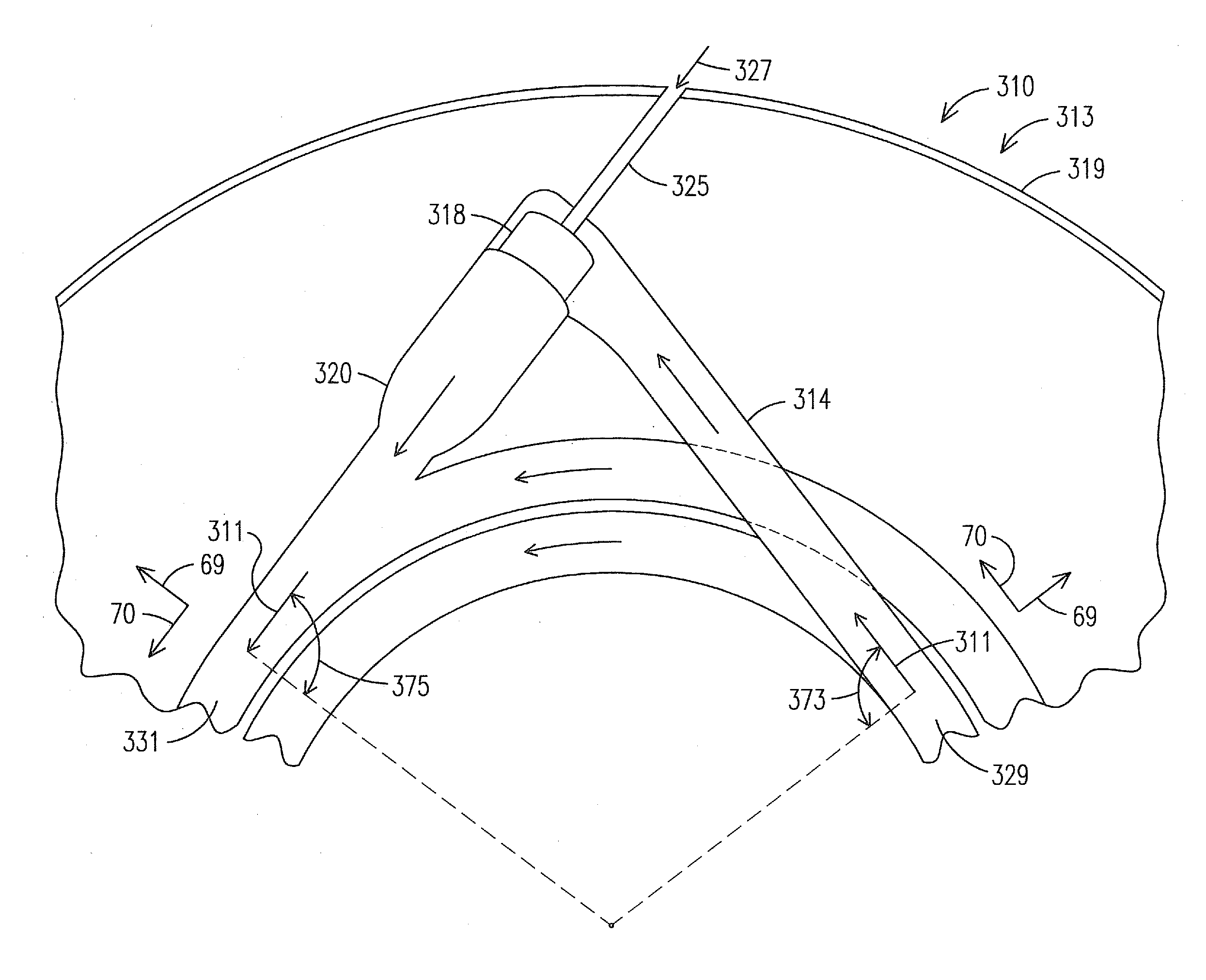
[0023]As discussed above, the inventors of the present invention recognized that an improved midframe portion of the gas turbine engine features initiating a mixed air flow (axial, tangential plus radial flow velocities) from the diffuser outlet. By initiating the mixed-air flow from the diffuser outlet, the air flow passes from the diffuser outlet to the combustor head inlet while undergoing a reduced total angle of rotation when compared to the air flow with the conventional midframe portion.

[0024]A midframe design is provided, in which a mixed air flow can be initiated within a diffuser of the midframe portion, downstream of the traditional axial compressor section. FIG. 4 illustrates a longitudinal cross-sectional view of a midframe portion 313 of a gas turbine engine 310 within a radial-tangential plane, in which a compressor section (not shown) compresses an air flow into an annulus 329 downstream of the compressor section. A plurality of diffuser ducts 314 are positioned in a...


PUM


Abstract

A midframe portion (313) of a gas turbine engine (310) is presented and includes a compressor section with a last stage blade to orient an air flow (311) at a first angle (372). The midframe portion (313) further includes a turbine section with a first stage blade to receive the air flow (311) oriented at a second angle (374). The midframe portion (313) further includes a manifold (314) to directly couple the air flow (311) from the compressor section to a combustor head (318) upstream of the turbine section. The combustor head (318) introduces an offset angle in the air flow (311) from the first angle (372) to the second angle (374) to discharge the air flow (311) from the combustor head (318) at the second angle (374). While introducing the offset angle, the combustor head (318) at least maintains or augments the first angle (372).

Description

STATEMENT REGARDING FEDERALLY SPONSORED DEVELOPMENT[0001]Development for this invention was supported in part by Contract No. DE-FC26-05NT42644, awarded by the United States Department of Energy. Accordingly, the United States Government may have certain rights in this invention.FIELD OF THE INVENTION[0002]The invention relates to can-annular gas turbine engines, and more specifically, to a midframe portion of a can-annular gas turbine engine.BACKGROUND OF THE INVENTION[0003]A conventional midframe design for a can-annular gas turbine engine is discussed in U.S. Pat. No. 7,721,547 (“'547 Patent”), assigned to the assignee of the present invention, which is incorporated by reference herein. FIG. 1 of the '547 Patent is reproduced as FIG. 1 herein, and illustrates a cross-section through a midframe portion 13 of a conventional can-annular gas turbine engine 10. The major components of the gas turbine engine 10 are a compressor section 12, a combustion section 16 and a turbine section ...

Claims


Application Information

Patent Timeline
Patent Type & Authority Applications(United States)
IPC IPC(8): F02G1/00
CPCF02C3/145F01D9/023F02C3/14F23R3/425
Inventor LITTLE, DAVID A.SCHILP, REINHARDROSS, CHRISTOPHER W.
Owner SIEMENS ENERGY INC
Why Eureka
Try Eureka