Exhaust gas recirculation arrangement with condensate discharge

a condensate discharge and exhaust gas technology, applied in the direction of combustion engines, non-fuel substance addition to fuel, charge feed systems, etc., can solve the problems of sulphuric acid or sulphurous acid, and the condensate cannot be re-evaporated at very high temperatures

Inactive Publication Date: 2013-08-29
DAIMLER AG
View PDF18 Cites 19 Cited by
  • Summary
  • Abstract
  • Description
  • Claims
  • Application Information

AI Technical Summary

Benefits of technology

[0011]In an exhaust gas recirculation arrangement in which condensate is discharged from an exhaust gas recirculation path of an internal combustion engine, in particular of a motor vehicle, wherein, due to a pressure difference between a condensate collection region arranged in the EGR path and a condensate discha

Problems solved by technology

Above all, for sulphur-containing fuel, it is problematical to have sulphuric acid or sulphurous acid or a mixture

Method used


Image

  • Exhaust gas recirculation arrangement with condensate discharge
  • Exhaust gas recirculation arrangement with condensate discharge
  • Exhaust gas recirculation arrangement with condensate discharge

Examples


Embodiment Construction

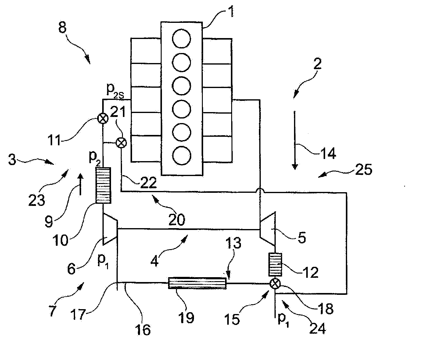
[0029]An internal combustion engine 1 as shown in FIG. 1 is equipped with an exhaust gas path 2 and a fresh air supply system 3, as well as a charging device 4. A turbine 5 of the charging device 4 is driven by means of the exhaust gas flowing in the exhaust gas path 2. The fluids flowing in the fresh air path 3 are compressed by means of a compressor 6 of the charging device 4. Thus, the fresh air path 3 is divided into a low-pressure region 7 and a high-pressure region 8. The low-pressure region 7 is arranged before the compressor 6 in the fresh air flow direction 9 and the high-pressure region 8 is arranged after the compressor 6. Likewise, a heat exchanger 10 in the form of a charge air cooler is arranged in the fresh air path 3 downstream of the compressor 6 and a restrictor element 11, with which the fresh air supply to the internal combustion engine 1 can be limited, is arranged downstream of the heat exchanger 10 which is in the form of a charge air cooler. A pressure p1 is ...


PUM


Abstract

In an exhaust gas recirculation arrangement in which condensate is discharged from an exhaust gas recirculation path of an internal combustion engine, in particular of a motor vehicle, wherein, due to a pressure difference between a condensate collection region arranged in the EGR path and a condensate discharge region, collected condensate is discharged at least partially from the condensate collection region into the condensate discharge region, when the pressure level prevalent in the condensate collection region is greater than in the condensate discharge region in a secure manner and with low environmental impact.

Description

[0001]This is a Continuation-In-Part application of pending international patent application PCT / EP2011 / 004692 filed Sep. 20, 2011 and claiming the priority of German patent application 10 2010 048 465.2 filed Oct. 14, 2010.BACKGROUND OF THE INVENTION[0002]The present invention relates to an exhaust gas recirculation arrangement for discharging condensate from an EGR path (EGR—exhaust gas recirculation) of an internal combustion engine. The invention also relates to an exhaust gas unit with such an EGR arrangement.[0003]In internal combustion engines with exhaust gas recirculation (EGR), a specific proportion of the exhaust gas is fed back to the combustion engine via an EGR path. Under specific conditions, condensate can be discharged from the exhaust gas or from an exhaust gas / air mixture in the EGR path. The condensate can lead to sooting and corrosion of the components in the EGR path. It is thus desirable to remove the condensate from the EGR path as quickly and completely as p...

Claims


Application Information

Patent Timeline
IPC IPC(8): F02M25/07
CPCF02M25/0732F02M25/07Y02T10/121F02M25/074F02M26/00F02M26/24F02M26/35
Inventor KOCH, THOMASRITZINGER, JOHANNES
Owner DAIMLER AG
Why Eureka
Try Eureka