Fuel Injection Strategy for Internal Combustion Engine Having Dedicated EGR Cylinders

a technology of internal combustion engine and fuel injection strategy, which is applied in the direction of machines/engines, electrical control, mechanical equipment, etc., can solve the problem of reducing the production of nox

Active Publication Date: 2013-08-29
SOUTHWEST RES INST
View PDF13 Cites 37 Cited by
  • Summary
  • Abstract
  • Description
  • Claims
  • Application Information

AI Technical Summary

Problems solved by technology

The dilution of the oxygen present in the com

Method used


Image

  • Fuel Injection Strategy for Internal Combustion Engine Having Dedicated EGR Cylinders
  • Fuel Injection Strategy for Internal Combustion Engine Having Dedicated EGR Cylinders
  • Fuel Injection Strategy for Internal Combustion Engine Having Dedicated EGR Cylinders

Examples


Embodiment Construction

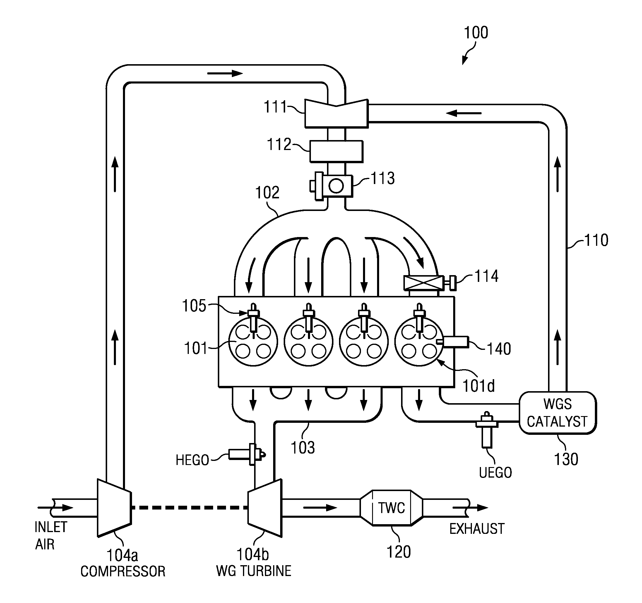
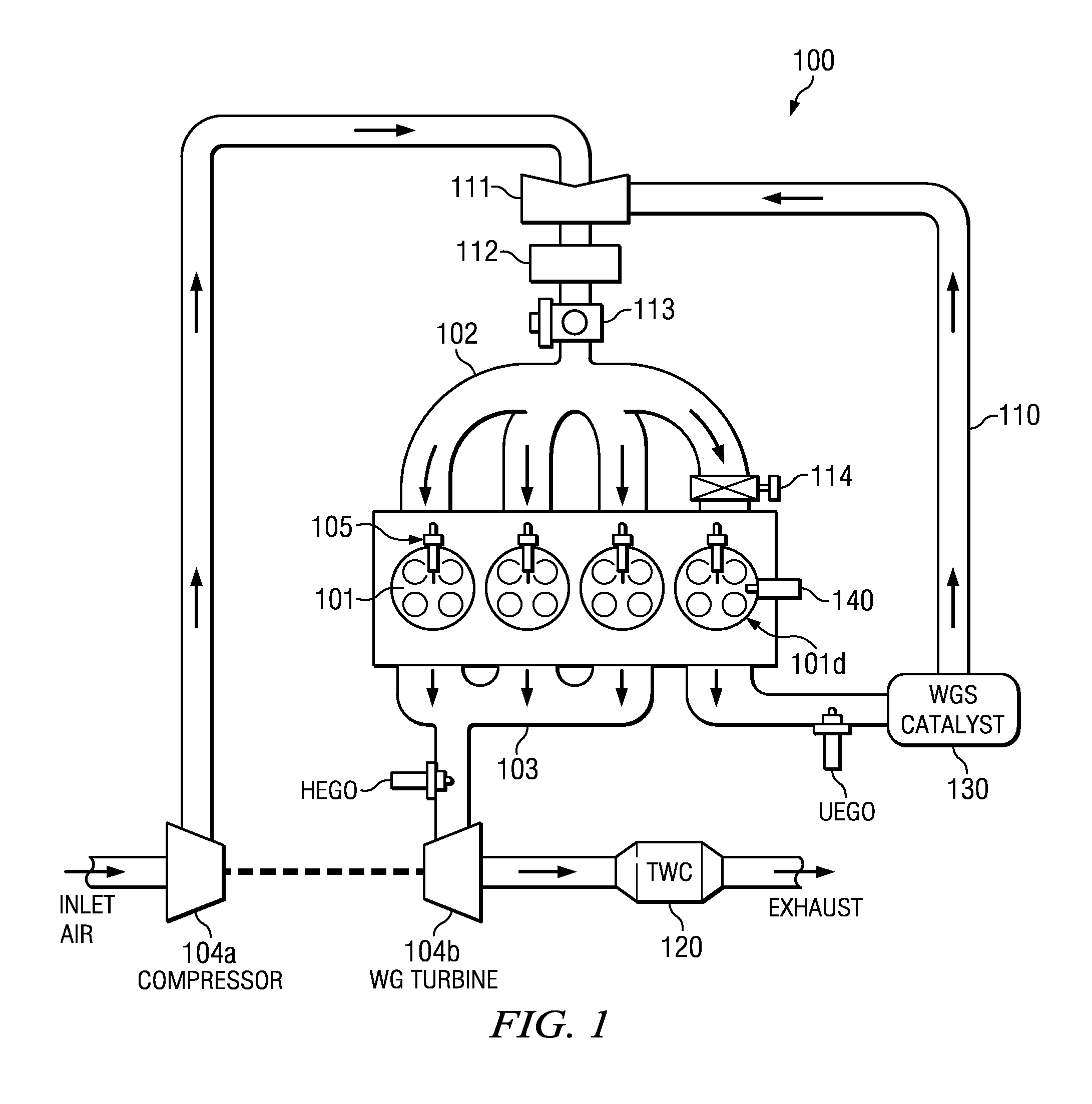
[0013]The following description is directed to a fuel injection method for use with an internal combustion engine having dedicated EGR. In a “dedicated EGR” engine, one or more of the engine's cylinders is used to generate exhaust gas to be recirculated and used as a diluent for the intake charge of the entire engine. The entire exhaust gas output of the dedicated EGR cylinder is recirculated, typically back to all cylinders. None of the exhaust of the non-dedicated EGR cylinders is recirculated.

[0014]A feature of dedicated EGR is that the composition of the exhaust gas from the dedicated cylinder(s) is controlled to be different from that of the exhaust of the non-dedicated cylinders. Specifically, the EGR composition is changed to improve combustion on all cylinders as compared to EGR in non dedicated EGR systems. U.S. patent application Ser. No. 12 / 140,878, entitled “EGR System with Dedicated EGR Cylinders”, to Alger, et al, discusses dedicated EGR and is incorporated by referenc...


PUM


Abstract

A method using exhaust gas recirculation (EGR) in an internal combustion engine. The engine has at least one “dedicated EGR cylinder”, whose entire exhaust is recirculated back to all the engine cylinders. The dedicated EGR cylinder is operated at a rich air-fuel ratio, and the other cylinders are operated stoichiometrically so that a conventional three way catalyst may be used to treat the exhaust. A fuel injector is used to inject fuel into the combustion chamber of the dedicated EGR cylinder after initiation of the main combustion event. This post injection method overcomes flammability limits of a dedicated EGR cylinder, and increases the hydrogen (H2) and carbon monoxide (CO) in its exhaust.

Description

TECHNICAL FIELD OF THE INVENTION[0001]This invention relates to internal combustion engines, and more particularly to an improved exhaust gas recirculation system for such engines.BACKGROUND OF THE INVENTION[0002]For many internal combustion engines, their engine control strategy has three important parameters: spark timing (or fuel injection timing in a diesel engine), the exhaust gas recirculation (EGR) rate and the air / fuel ratio (AFR).[0003]To implement EGR, a fraction of the exhaust gas is recycled from the exhaust system back to the intake system. The recirculated exhaust gas is mixed with the fresh fuel-air mixture before entering the cylinders. EGR can be implemented in internal and external configurations. External configurations can be implemented as either a high pressure or low pressure loop, depending on whether the recirculated exhaust is introduced to the intake post compressor (high pressure loop) or pre-compressor (low pressure loop).[0004]EGR has a long history of ...

Claims


Application Information

Patent Timeline
IPC IPC(8): F02B47/08F02M25/07
CPCY02T10/121F02M25/07F01N3/0842F01N3/2066F02B37/00F02D41/006F02D41/0065F02D41/008F02D41/405F02D2021/083F02M26/35F02M26/43Y02T10/40
Inventor GINGRICH, JESS W.ALGER, II, TERRENCE F.GUKELBERGER, RAPHAEL
Owner SOUTHWEST RES INST
Why Eureka
Try Eureka