Eureka AIR delivers breakthrough ideas for toughest innovation challenges, trusted by R&D personnel around the world.

Installation for preparing batches of products, of the vial or bottle kind or the like

Inactive Publication Date: 2013-08-29
C E R M E X CONSTR ETUD & RECH DE MATERIELS POUR LEMBALLAGE DEXPEDITION
View PDF6 Cites 12 Cited by
  • Summary
  • Abstract
  • Description
  • Claims
  • Application Information

AI Technical Summary

Benefits of technology

The invention is a conveyor system that prevents instability and unbalance of products as they pass through the conveyor modules. This is achieved by using a unique arrangement of rollers called "sabres" which helps to stabilize the products and reduce the risk of damage during transportation. The conveyor modules have an endless belt that winds over a first "sabre" roller of the same module, as well as over a second "sabre" roller of the downstream conveyor. This arrangement improves the compactness of the installation and allows for direct support of conveying modules and rails without adding bulk to the overall length.

Problems solved by technology

In this type of installation, it is more complicated to prepare batches from relatively flexible products, due to the difficulty in creating a well-organized leading side exiting the regulating unit.
This dead plate retains the products and can cause deformations in the products in the line, to the point of interfering with their alignment and destabilizing the leading side of the products.
The belt of the conveying module advances at a speed which is substantially equal to that of the regulating fingers, or even slightly below, but this belt speed is not truly controlled because said belt is subjected to forces which can cause this speed to vary.
These variations in speed may result from friction and stresses due to pressure from the products located upstream and downstream of the regulating fingers.
These lubricants spread onto the pulleys and the belts, generating sliding phenomena that is difficult to manage and control.
However, due to improvements in production speeds and the appearance of new products which are sometimes more difficult to manipulate, users of these batch preparation machines are increasingly confronted with difficulties which they can only resolve using specific machines adapted to each case, meaning for only one or a few types of products, according to their size, stability, and capacity to retain a shape compatible with the ungrouping elements.

Method used


Image

  • Installation for preparing batches of products, of the vial or bottle kind or the like
  • Installation for preparing batches of products, of the vial or bottle kind or the like
  • Installation for preparing batches of products, of the vial or bottle kind or the like

Examples


Embodiment Construction

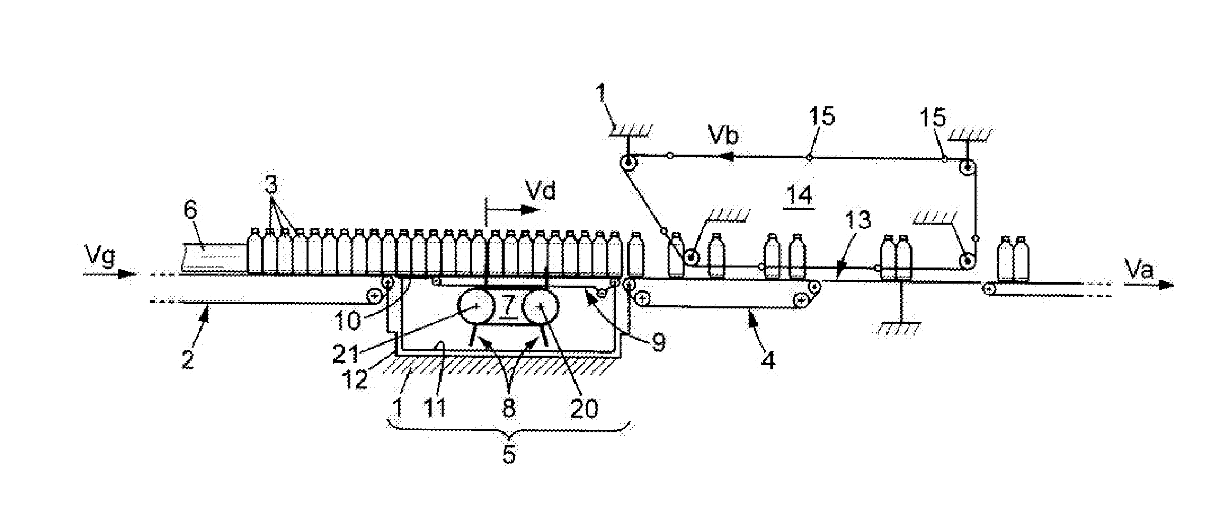
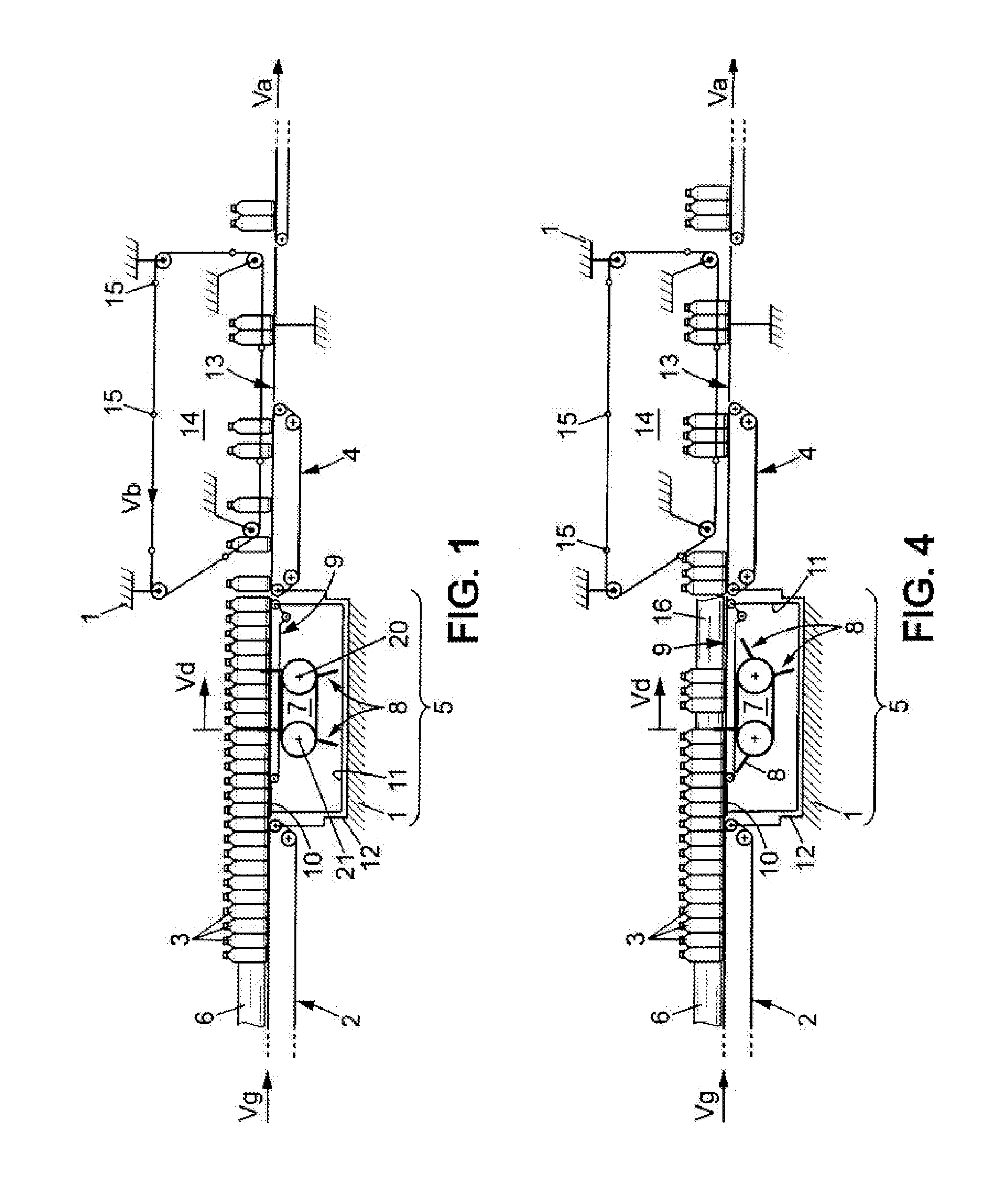
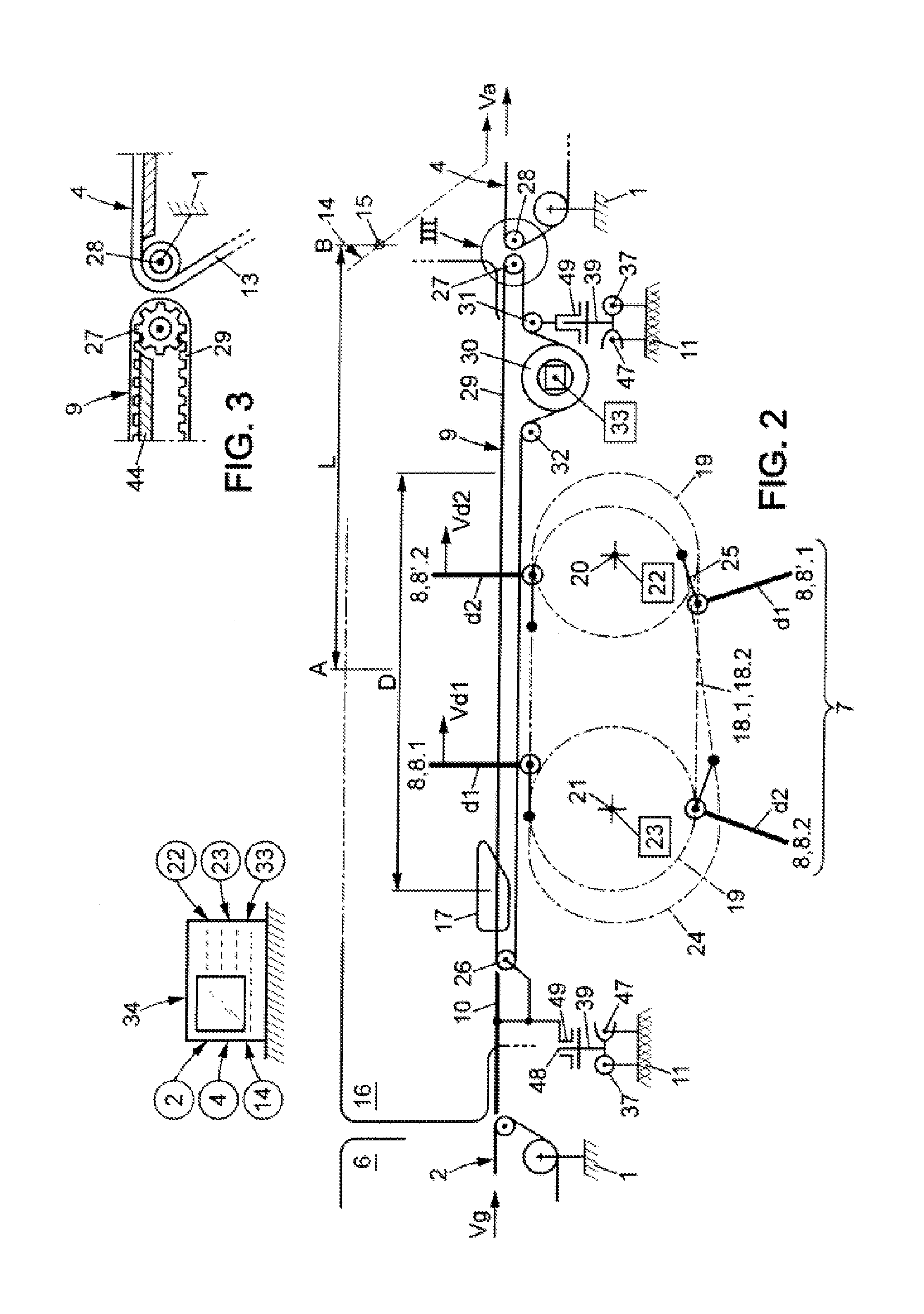
[0042]The installation represented in FIG. 1 comprises a general frame 1 onto which are assembled:[0043]an upstream feeder conveyor 2 which has an endless belt and which conveys in a continuous manner and at a speed Vg a stream of products 3 and in particular of products having a circular or oval cross-section, or having facets, such as for example bottles, vials, etc.;[0044]a downstream conveying system which in particular comprises a downstream preparation conveyor 4, or supplying conveyor, which has an endless belt and which advances at a speed Va and which moves the batches of products towards a packaging machine, or other, not represented, and,[0045]a regulating unit 5 between said upstream conveyor and said downstream conveyor 4, said regulating unit controlling the speed at which the stream of products 3 advances.

[0046]These products 3 arrive in multiple lines at the upstream conveyor 2; they are guided by walls 6 which delimit passages, and these products then pass through t...


PUM


Abstract

The installation comprises:—an upstream conveyor (2) which supplies the lines of products, and a downstream conveying system, having, between the two;—a unit (5) for regulating the flow of products and, in each lane of said unit, a conveying module (9) of the endless belt type and sets of mobile fingers (8) for controlling the advancing speed of said products. The endless belt of each conveying module (9) extends as far as the inlet of the downstream conveyor (4), and control means are provided to separately adjust the speed of the sets of fingers (8) so as to ungroup the products in accordance with two separate modes:—an ungrouping mode with selection by regulated flow (SRF) and—an ungrouping mode with selection by adjustable fingers (SAF).

Description

TECHNICAL FIELD OF THE INVENTION[0001]The invention relates to an installation for preparing batches of bottle- or vial-type products or the like, in order to package them.TECHNOLOGICAL BACKGROUND OF THE INVENTION[0002]Feeding a continuous stream of batches of product to packaging machines can be done automatically by means of an installation of the type described, for example, in published PCT patent application no. WO 2010 / 037959.[0003]This installation is used to prepare batches from products having a circular or ovoid cross-section, such as bottles or other products, and comprises:[0004]an upstream conveyor which continuously supplies products arranged in single file in longitudinal passages,[0005]a conveying system arranged downstream for preparing the batches then transferring them to the packaging machine, and between the two,[0006]a unit for regulating the flow of products, said unit comprising a device for controlling the advance and transverse alignment of said products in...

Claims


Application Information

Patent Timeline
IPC IPC(8): B65G47/52
CPCB65B35/44B65G47/088B65G47/52B65G47/841B65G2201/0244B65G47/31
Inventor VASSE, MICHAELDANIERE, LIONELCHOPLIN, GREGORY
Owner C E R M E X CONSTR ETUD & RECH DE MATERIELS POUR LEMBALLAGE DEXPEDITION
Why Eureka
Eureka Blog
Learn More