
Dielectric barrier discharge lamp device, and optical fluid treatment device provided with the dielectric barrier discharge lamp device

a dielectric barrier and lamp device technology, applied in the direction of gas-filled discharge tubes, material analysis using wave/particle radiation, packaging, etc., can solve the problem of relatively large volume and achieve the effect of less costly and robust mechanical design

Active Publication Date: 2013-08-29
USHIO EURO
View PDF24 Cites 6 Cited by
  • Summary
  • Abstract
  • Description
  • Claims
  • Application Information

AI Technical Summary

Benefits of technology

The patent describes a new type of lamp called a dielectric barrier discharge (DBD) lamp that can be used for fluid treatment. The lamp has a unique structure that allows for compact construction and is less costly than previous options. It also has a high voltage electrode that can be easily applied to the lamp. The technical effects of this invention are its compact size, lower cost, and improved mechanical design for fluid treatment.

Problems solved by technology

A disadvantage of the arrangement according to the reference WO2010079401 is its relatively large volume.
A further disadvantage results from the measures that need to be taken to ensure that the lamp and the lamp driver housing, which are both in contact with the fluid to be treated, are sufficiently sealed to prevent deterioration of the lamp or the lamp driver due to corrosion or short-circuiting caused by fluid leakage.

Method used


Image

  • Dielectric barrier discharge lamp device, and optical fluid treatment device provided with the dielectric barrier discharge lamp device
  • Dielectric barrier discharge lamp device, and optical fluid treatment device provided with the dielectric barrier discharge lamp device
  • Dielectric barrier discharge lamp device, and optical fluid treatment device provided with the dielectric barrier discharge lamp device

Examples


Embodiment Construction

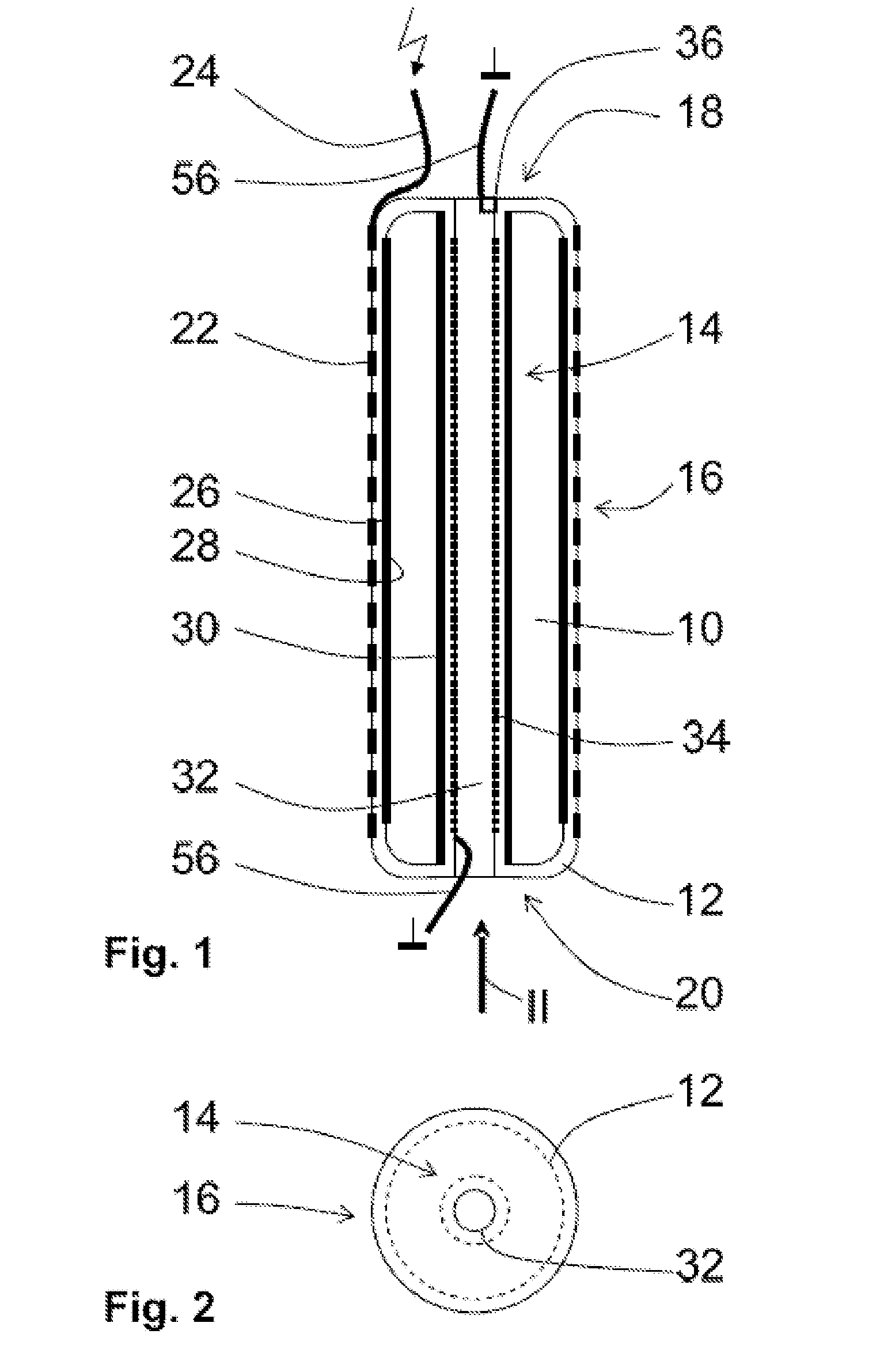
[0035]FIG. 1 and FIG. 2 depict a part of an embodiment of a dielectric barrier discharge, DBD, lamp device. A discharge chamber 10 is defined by a toroid-shaped discharge chamber wall 12. The discharge chamber wall 12 comprises a generally tubular inner wall section 14 having a length, a generally tubular outer wall section 16 having a length, a first generally ring-shaped end wall section 18 extending between a first end of the outer wall section 16 and the inner wall section 14, and a second generally ring-shaped end wall section 20 extending between a second end of the outer wall section 16, opposite the first end of the outer wall section 16, and the inner wall section 14. In FIG. 1, the lengths of the inner wall section 14 and the outer wall section 16 extend in the direction of arrow II.

In an embodiment, the inner wall section 14, the first and second end wall sections 18, 20, and the outer wall section 16 (and consequently the entire discharge chamber wall 12) are made in one...


PUM


Abstract

A dielectric barrier discharge, DBD, lamp device comprises a toroid shaped discharge chamber (10) having a discharge chamber wall (12). The discharge chamber wall comprises a tubular inner wall section (14), a tubular outer wall section (16), and two ring-shaped end wall sections (18, 20). Each of the end wall sections extend between an end of the outer wall section and an end of the inner wall section. A high voltage electrode (22) is provided at an outer surface of the outer wall section of the discharge chamber wall. A low voltage electrode comprises an electrically conducting fluid surrounded by the inner wall section of the discharge chamber wall. The DBD lamp device may be part of an optical fluid treatment device.

Description

FIELD OF THE INVENTION[0001]The invention relates to the field of dielectric barrier discharge, DBD, lamp devices, and more specifically to a discharge chamber of a DBD lamp device. The invention further relates to an optical fluid treatment device provided with the DBD lamp device of the invention.[0002]An optical fluid treatment device, which may also be referred to as an optical reactor or a photo-reactor, may provide an optical treatment of a fluid, such as sterilization, disinfection, killing or de-activating micro-organisms, oxidation or decomposition of matter by means of light, in particular, but not exclusively, by ultraviolet, UV, light, such as UV-C light.BACKGROUND OF THE INVENTION[0003]In an optical fluid treatment device, a light source is used to treat a fluid. The light source generates light at an appropriate wavelength, or at different appropriate wavelengths, for a fluid to be treated in a desired manner. The light generated by the light source is supplied to the ...

Claims


Application Information

Patent Timeline
IPC IPC(8): H01J61/30A61L2/08
CPCH01J65/046C02F1/003C02F1/325C02F2201/3223C02F2201/326C02F2307/04H01J65/08H01J61/32A61L2/08H01J61/30H01J5/48H01J19/57C02F2307/06B67D2210/00015B67D1/07B67D2001/075
Inventor MASTENBROEK, OLAFBAK, ROBERTGEBOERS, JACQUES MARIA JOZEFVAN DER MEER, MICHIEL
Owner USHIO EURO
Learn More