
Fault direction parameter indicator device and related methods

Active Publication Date: 2013-08-29
ABB (SCHWEIZ) AG
View PDF6 Cites 39 Cited by
  • Summary
  • Abstract
  • Description
  • Claims
  • Application Information

AI Technical Summary

Benefits of technology

The invention provides a way to detect faults in a way that is reliable and efficient while also reducing costs. This is possible because no voltage measurements are needed, and the calculations used in the process are simple and can be performed quickly with limited hardware.

Problems solved by technology

This approach becomes unreliable when the fault is in close proximity to the relay, because in this case, the relay is almost grounded by the short circuit (industrially termed as ‘close-in faults’).
Further, overcurrent relays including a voltage measurement unit are expensive.
Since they have to be used in large number for the above arrangement, this is a major cost factor.

Method used


Image

  • Fault direction parameter indicator device and related methods
  • Fault direction parameter indicator device and related methods
  • Fault direction parameter indicator device and related methods

Examples


Embodiment Construction

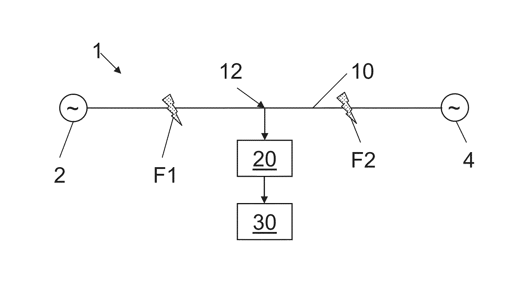
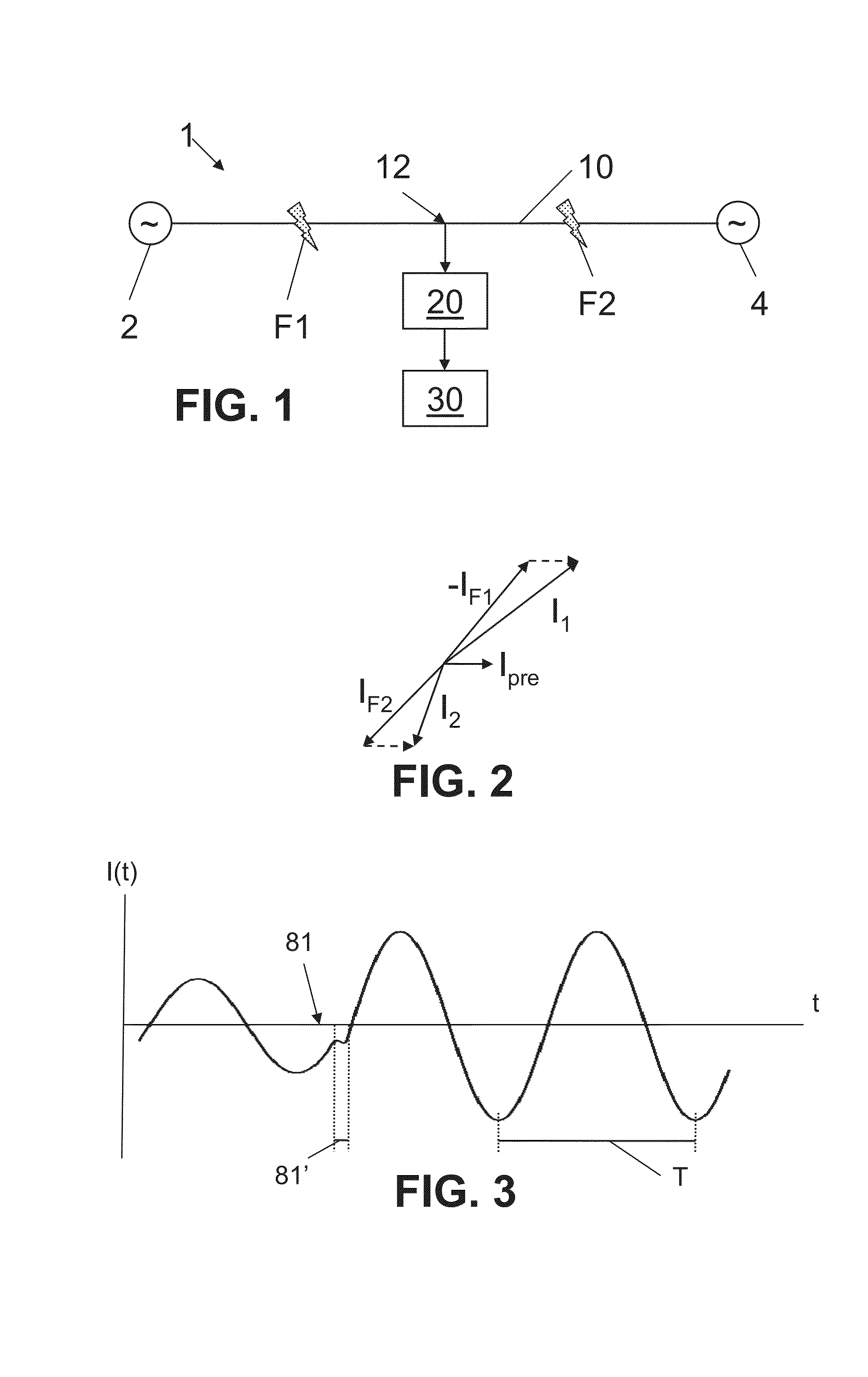
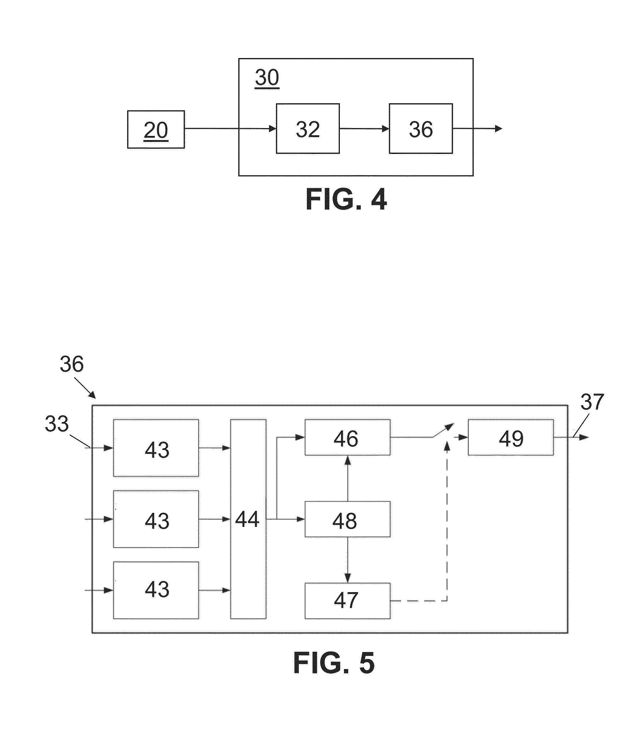
[0028]Exemplary embodiments of the present disclosure provide a method of determining a fault direction parameter of a fault on an AC transmission line of a power distribution system relative to a measurement location of the transmission line. Exemplary embodiments of the present disclosure also provide a fault direction parameter indicator device for indicating a fault direction parameter of a fault on an AC transmission line of a power distribution system relative to a measurement location of the transmission line. In addition, exemplary embodiments of the present disclosure provide a directional overcurrent relay including such a fault direction parameter indicator device and a circuit breaker which is operatively coupled to the fault direction indicator device and configured to receive the fault direction parameter from the fault direction parameter indicator device. Moreover, exemplary embodiments of the present disclosure provide for an outdoor and / or smart grid power distribu...


PUM


Abstract

A method of determining a fault direction parameter of a fault on an AC transmission line of a power distribution system relative to a measurement location of the transmission line. The method includes measuring a time-dependent AC current of the transmission line at the measurement location to obtain time-domain current data indicative of the measured current, obtaining a time of the fault on the transmission line, identifying first and second times by identifying a periodically re-occurring feature of the current data, such that the fault time is between the first and second times, extracting, from the current data, an offset indicative parameter indicative of a time offset of the current at the fault time and between the first and second times, calculating an offset direction parameter by comparing the offset indicative parameter to a non-offset indicative parameter, and establishing the fault direction parameter based on the offset direction parameter.

Description

RELATED APPLICATIONS[0001]This application claims priority as a continuation application under 35 U.S.C. §120 to PCT / EP2011 / 067995, which was filed as an International Application on Oct. 14, 2011 designating the U.S., and which claims priority to European Application 10187546.6 filed in Europe Oct. 14, 2010. The entire contents of these applications are hereby incorporated by reference in their entireties.FIELD[0002]The present disclosure relates to a fault direction parameter indicator device for a power distribution system. More particularly, the present disclosure relates to a fault direction parameter indicator device for indicating a direction parameter of a fault on a transmission line. The present disclosure also relates to a directional overcurrent relay including such a fault direction parameter indicator device and a circuit breaker. In addition, the present disclosure relates to methods of determining a fault direction parameter of a fault on a transmission line of a pow...

Claims


Application Information

Patent Timeline
IPC IPC(8): G01R31/08
CPCG01R19/0092G01R31/025G01R31/08H02H3/081H02H3/265G01R31/085G01R31/52
Inventor UKIL, ABHISEKDECK, BERNHARDSHAH, VISHAL H.
Owner ABB (SCHWEIZ) AG
Learn More