Zoom lens, imaging device, and portable digital device

Inactive Publication Date: 2013-08-29
RICOH KK
View PDF1 Cites 14 Cited by
  • Summary
  • Abstract
  • Description
  • Claims
  • Application Information

AI Technical Summary

Benefits of technology

[0012]The present invention has been made in view of the above circumstances, and an object of the present invention is to provide a zoom lens which is suitable for a compact and high performance digital camera or the like, is able to increase an AF speed, downsize a driving s

Problems solved by technology

Therefore, a load for moving the focus group is increased, so that a motor which drives the focus group is increased in size, and thus, a long time is required for the focusing operation.
Therefore, a load for moving the focus group is increased similar to the case in Patent Document 1, so that a motor whi

Method used


Image

  • Zoom lens, imaging device, and portable digital device
  • Zoom lens, imaging device, and portable digital device
  • Zoom lens, imaging device, and portable digital device

Examples


Example

[0080]The ninth embodiment of the present invention relates to an imaging device such as a digital camera.

[0081]An imaging device according to the ninth embodiment of the present invention uses the above-described zoom lens as an imaging optical system. With this configuration, a compact and high performance imaging device such as a digital camera can be achieved. By using the zoom lens which satisfies the condition (1), the decrease in the summation Dg of the thickness of each lens group in the optical axis direction and the aberration correction can be well balanced. Therefore, such a zoom lens is suitable for an imaging device in which a lens is collapsed to be housed, and an exchangeable lens for an imaging device.

[0082]Next, specific embodiments based on the above embodiments will be described. The following Embodiments 1-8 are specific embodiments based on numerical examples of the zoom lenses according to the first to eighth embodiments of the present invention.

Example

[0083]FIGS. 1-4 are views describing a zoom lens in Embodiment 1 according to the first embodiment of the present invention. FIGS. 5-8 are views describing a zoom lens in Embodiment 2 according to the second embodiment of the present invention. FIGS. 9-12 are views describing a zoom lens in Embodiment 3 according to the third embodiment of the present invention. FIGS. 13-16 are views describing a zoom lens in Embodiment 4 according to the fourth embodiment of the present invention. FIGS. 17-20 are views describing a zoom lens in Embodiment 5 according to the fifth embodiment. FIGS. 21-24 are views describing a zoom lens in Embodiment 6 according to the sixth embodiment. FIGS. 25-28 are views describing a zoom lens in Embodiment 7 according to the seventh embodiment. FIGS. 29-32 are views describing a zoom lens in Embodiment 8 according to the eighth embodiment. In the zoom lens in each of Embodiments 1-8, an optical element made of a parallel plate disposed on the image surface side...

Example

Embodiment 2

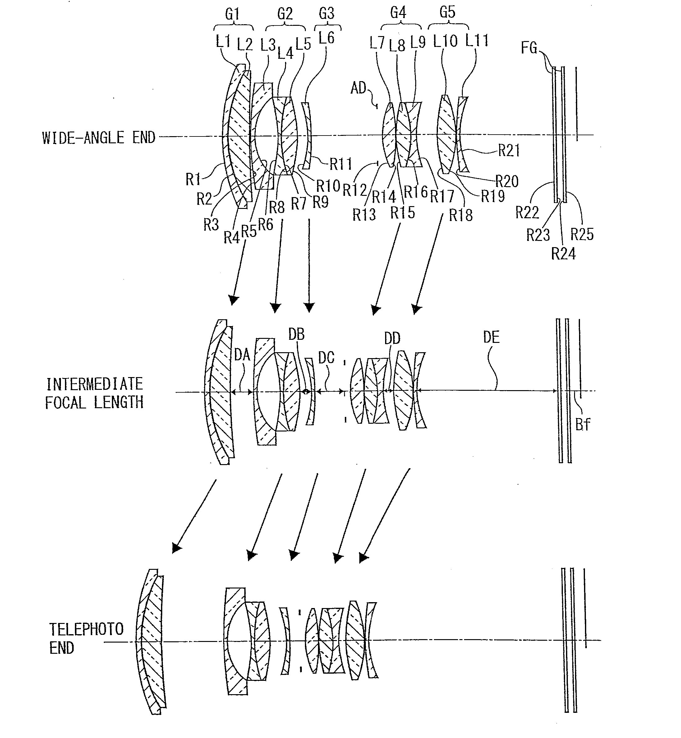
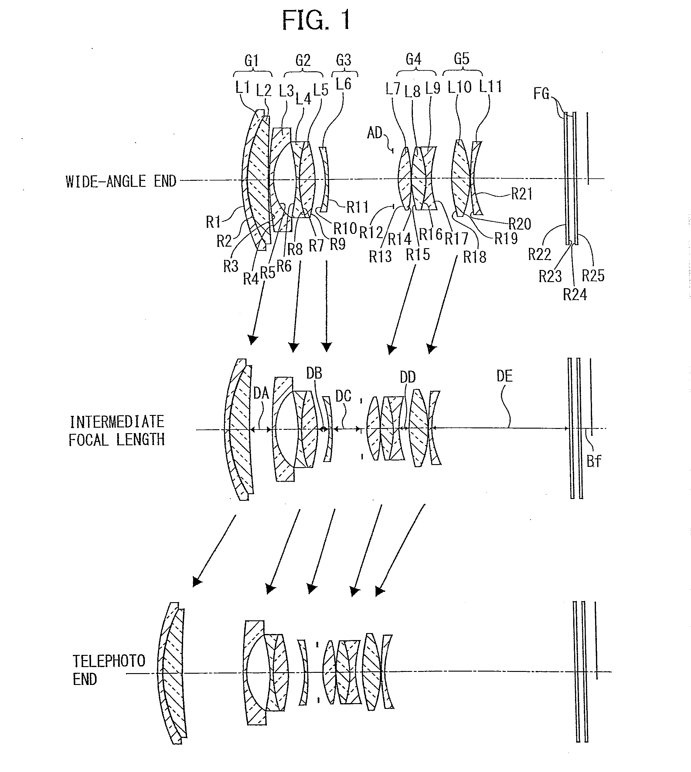
[0165]FIG. 5 provides sectional views along an optical axis in a wide-angle end, intermediate focal length and telephoto end, schematically illustrating a configuration of an optical system of a zoom lens and a zoom trajectory in Embodiment 2 according to the second embodiment of the present invention. In addition, in FIG. 5 illustrating the arrangement of lens groups of Embodiment 2, the left side is an object (subject) side.

[0166]The zoom lens illustrated in FIG. 5 includes in order from the object side along the optical axis a first lens group G1 having a positive refractive power, a second lens group G2 having a negative refractive power, a third lens group G3 having a negative refractive power, a fourth lens group G4 having a positive refractive power, a fifth lens group G5 having a positive refractive power, and an aperture stop AD disposed between the third and fourth lens groups G3, G4.

[0167]The first lens group G1 includes in order from the object side a first l...


PUM


Abstract

A zoom lens includes, in order from an object side along an optical axis, a first lens group having a positive refractive power, a second lens group having a negative refractive power, a third lens group having a negative refractive power, a fourth lens group having a positive refractive power, and a fifth lens group having a positive refractive power, wherein with a change in a magnification from a wide-angle end to a telephoto end, an interval between the first lens group and the second lens group is increased, the interval between the second lens group and the third lens group is changed, the interval between the third lens group and the fourth lens group is decreased, the interval between the fourth lens group and the fifth lens group is decreased, and focusing is performed by the third lens group.

Description

PRIORITY CLAIM[0001]The present application is based on and claims priority from Japanese Patent Application No. 2012-053886, filed on Mar. 10, 2012, and Japanese Patent Application No. 2012-043599, filed on Feb. 29, 2012, the disclosures of which are hereby incorporated by reference in their entirety.BACKGROUND[0002]1. Field of the Invention[0003]The present invention relates to a zoom lens having a function which changes an angle of view by changing a focal distance, and a zoom lens suitable for an imaging device which obtains subject image data by using an imaging element. In particular, the present invention relates to a compact zoom lens suitable for a digital camera which images a still image, a video camera which images a moving image or the like, an imaging device and a portable digital device using such a zoom lens as an imaging optical system.[0004]2. Description of the Related Art[0005]In recent years, widespread digital cameras are requested to be further downsized and t...

Claims


Application Information

Patent Timeline
IPC IPC(8): G02B15/14
CPCG02B13/009G02B15/14G02B15/17G02B15/145125
Inventor ATSUUMI, HIROMICHITAKANO, YOHEI
Owner RICOH KK
Why Eureka
Try Eureka