System for correcting thermal displacement of machine tool
Inactive Publication Date: 2013-08-29
MITSUBISHI HEAVY IND LTD
View PDF6 Cites 20 Cited by
Summary
Abstract
Description
Claims
Application Information
AI Technical Summary
This helps you quickly interpret patents by identifying the three key elements:
Problems solved by technology
Method used
Benefits of technology
Benefits of technology
The thermal displacement correction system for a machine tool described in this patent is designed to correct the position of a machine tool when it is subject to temperature changes. The system includes a spindle with a tool mounted thereto, a column, a support member for the spindle system, a table movable in the X-axis direction, and position sensors on the spindle and table to detect their positions. The system also includes temperature sensors on the support member and column to measure their temperatures. The system calculates the amount of thermal displacement of the spindle system and table with reference to the column's temperature data, and uses this information to perform accurate displacement correction. The technical effects of this system are improved accuracy and efficiency of machine tool positioning even under temperature variations.
Problems solved by technology
Deterioration in static accuracy due to mechanical displacement as described above, in particular, deterioration in static accuracy due to mechanical displacement resulting from heat or the like, is a major cause of increase in machining error and is still a major problem today.
Method used
Image
Click on the blue label to locate the original text in one second.
Reading with bidirectional positioning of images and text.
Examples
embodiment 1
[0104]Based on FIGS. 1 to 3, a thermal displacement correction system for a machine tool according to Embodiment 1 of the present invention will be described.
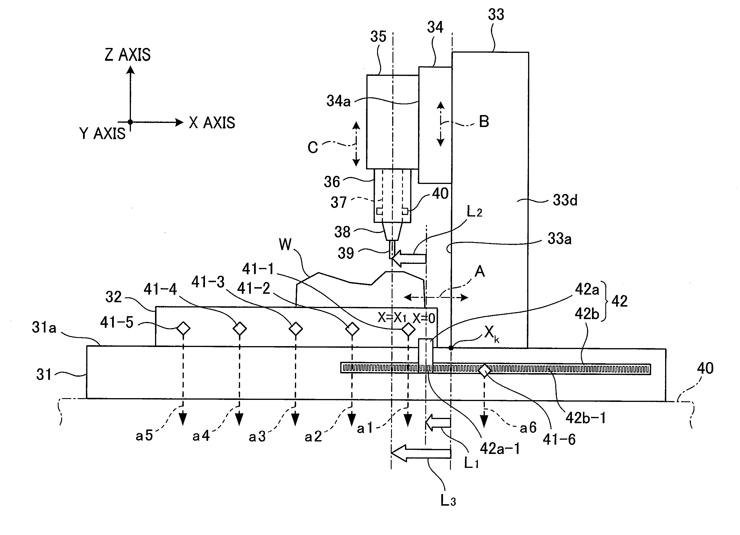
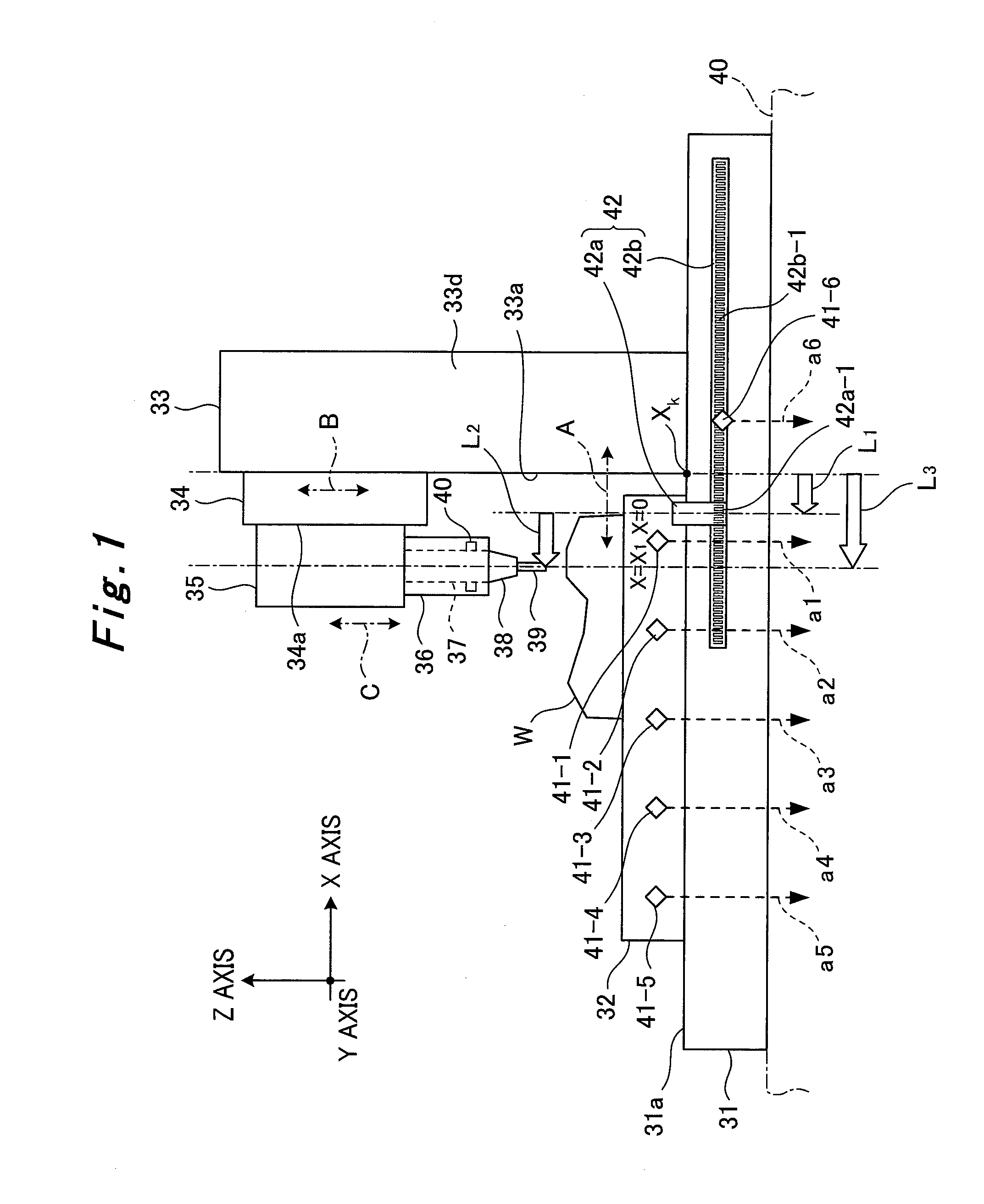
[0105]As shown in FIG. 1, a machine tool includes: a bed 31; a table 32; a gate-shaped column 33; a cross rail 34; a saddle 35; a ram 36; a spindle 37 incorporated in the ram 36 in a rotatably supported state; a tool 39 mounted to the spindle 37 through an attachment 38; and a position detector 42.
[0106]The bed 31 is disposed on a floor surface 40. The table 32 and the column 33 are disposed on the bed 31. A workpiece W is placed on the table 32. The table 32 is movable straightly along guiderails (not shown) laid on an upper surface 31a of the bed 31 in a horizontal X-axis direction (the front-rear direction of the column 33) as illustrated with arrow A by means of a feed mechanism (not shown in FIG. 1; see FIG. 2). The cross rail 34 is disposed on a front surface 33a of the column 33, and is movable straightly along guiderail...
embodiment 2
[0132]Based on FIGS. 4 and 5, a thermal displacement correction system for a machine tool according to Embodiment 2 of the present invention will be described. Note that in the thermal displacement correction system shown in FIGS. 4 and 5, the same portions as those of the thermal displacement correction system of Embodiment 1 described above will be denoted by the same reference numerals, and overlapping descriptions thereof will be omitted.
[0133]As shown in FIG. 4, in Embodiment 2, multiple temperature sensors 41-7, 41-8, 41-9, and 41-10 are further disposed in the machine tool, in addition to the same temperature sensors 41-1 to 41-6 as those described above.
[0134]The cross-rail temperature sensor 41-7 is disposed in the cross rail 34, detects the temperature of the cross rail 34, and outputs detected temperature data a7 to the machine tool's displacement correction device 81 (see FIG. 5; details will be described later). The saddle temperature sensor 41-8 is disposed in the sadd...
embodiment 3
[0144]Based on FIGS. 6 to 9, a thermal displacement correction system for a machine tool according to Embodiment 3 of the present invention will be described. Note that in the thermal displacement correction system shown in FIGS. 6 and 7, the same portions as those of the thermal displacement correction systems of Embodiments 1 and 2 described above will be denoted by the same reference numerals, and overlapping descriptions thereof will be omitted.
[0145]As shown in FIG. 6, in Embodiment 3, multiple temperature sensors 41-11, 41-12, 41-13, 41-14, 41-15, and 41-16 are further disposed in the machine tool, in addition to the same temperature sensors 41-1 to 41-10 as those described above.
[0146]The column temperature sensors 41-11, 41-12, and 41-13 are disposed in upper, middle, and lower portions of the column 33 on the front surface 33a side, detect the temperatures of these upper, middle, and lower portions, and output pieces of detected temperature data all, a12, and a13 to the mac...
PUM
Property
Measurement
Unit
Temperature
aaaaa
aaaaa
Displacement
aaaaa
aaaaa
Abstract
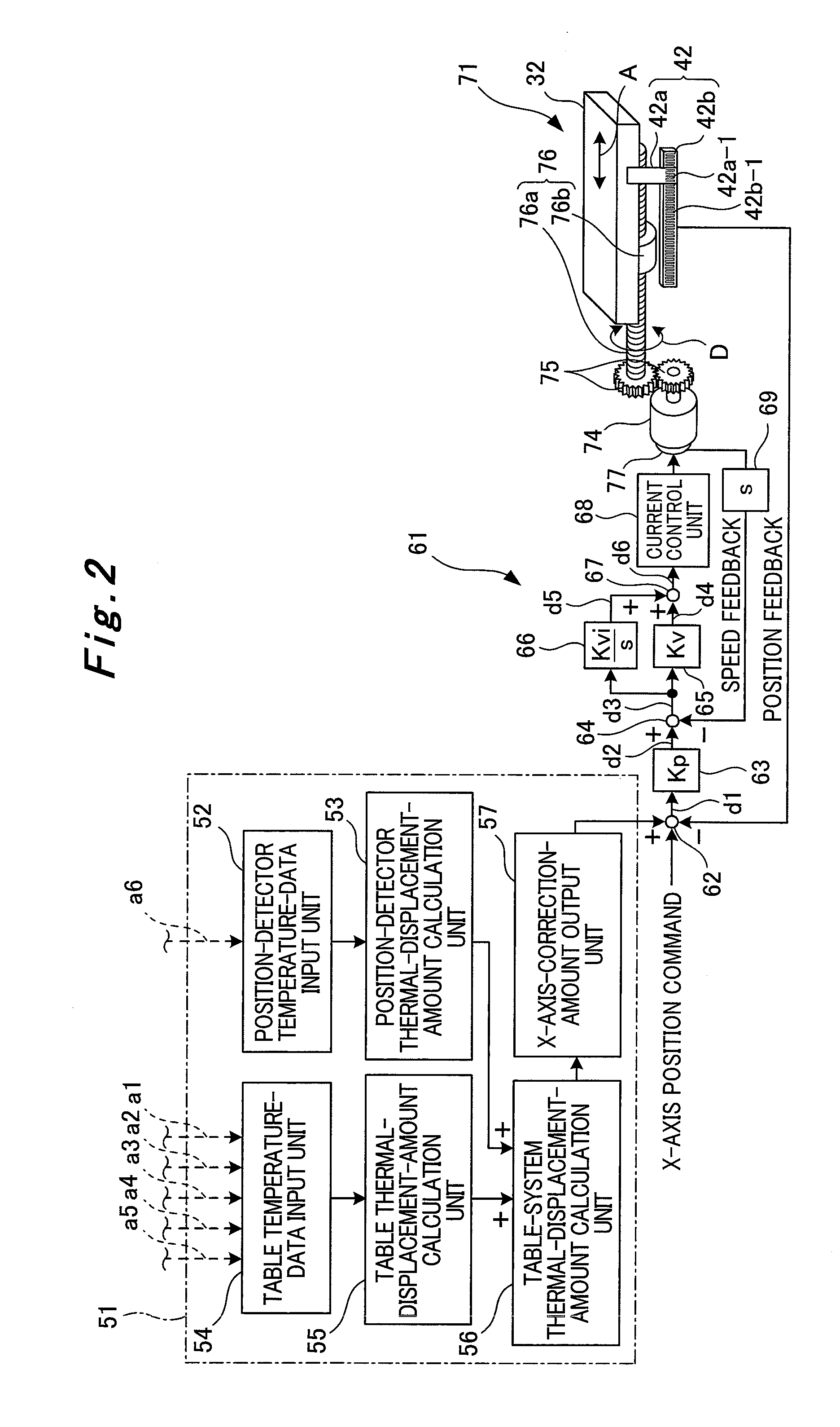
The purpose of the present invention is to provide a system for correcting thermal displacement of a machine tool, said system being capable of evaluating the amount of thermal displacement with a column front face serving as a reference position, and being capable of performing thermal displacement correction with good precision even when the amount of thermal displacement of a table is not uniform. For this purpose, the system is provided with, for example: a position detector temperature sensor (41-6); table temperature sensors (41-1 to 41-5); and a displacement correction device. The displacement correction device comprises: a temperature data input section for inputting temperature data (a6); a thermal displacement amount calculation section for calculating the amount of thermal displacement of the position detector on the basis of the temperature data (a6); a temperature data input section for inputting temperature data (a1 to a5); a thermal displacement amount calculation section for calculating, on the basis of the temperature data (a1 to a5), the amount of thermal displacement of the table corresponding to a temperature distribution in the X axis direction; a thermal displacement amount calculation section for calculating the amount of thermal displacement of the table system with the column front face serving as the reference position, said calculation being performed on the basis of the amount of thermal displacement of the table and the amount of thermal displacement of the position detector; and an X axis correction amount output section for outputting an X axis correction amount on the basis of the amount of thermal displacement of the table system.
Description
TECHNICAL FIELD[0001]The present invention relates to a thermal displacement correction system for a machine tool.BACKGROUND ART[0002]Generally, machine tools and the like employ, for their control systems, a fully-closed-loop feedback control system as shown in FIG. 12 in which positional information on a mechanical end is detected by a position detector 1 and used as a position feedback. Here, mechanical displacement is caused by heat sources such as a spindle and a servomotor 2 given inside the machine and changes in ambient temperature. The mechanical displacement deteriorates static accuracies such as the accuracy of positioning on each movement axis and the accuracy of positioning in a three-dimensional space. Note that the mechanical displacement occurs not only by thermal displacement but also by deflection with the machine's own weight and the like.[0003]Further, in a case of employing a semi-closed loopfeedback control system as shown in FIG. 13 for a control system of a ...
Claims
Application Information
Patent Timeline
Application Date:The date an application was filed.
Publication Date:The date a patent or application was officially published.
First Publication Date:The earliest publication date of a patent with the same application number.
Issue Date:Publication date of the patent grant document.
PCT Entry Date:The Entry date of PCT National Phase.
Estimated Expiry Date:The statutory expiry date of a patent right according to the Patent Law, and it is the longest term of protection that the patent right can achieve without the termination of the patent right due to other reasons(Term extension factor has been taken into account ).
Invalid Date:Actual expiry date is based on effective date or publication date of legal transaction data of invalid patent.

