Angular sector of a stator for a turbine engine compressor, a turbine engine stator, and a turbine engine including such a sector

a turbine engine and stator technology, applied in the field of stators, can solve the problems of affecting the damping effect the risk of damage or even destruction and the inability to provide satisfactory damping of the leading and trailing edges of the vanes

Active Publication Date: 2013-08-29
SN DETUDE & DE CONSTR DE MOTEURS DAVIATION S N E C M A
View PDF11 Cites 13 Cited by
  • Summary
  • Abstract
  • Description
  • Claims
  • Application Information

AI Technical Summary

Benefits of technology

[0009]The present invention seeks to propose a stator angular sector that is effective in limiting the mechanical stresses to which each vane of the stator sector is subjected in operation, in particular at its leading and / or trailing edges.

Problems solved by technology

Since these connection zones are thin and not very strong, there is a risk of the leading and trailing edges being damaged or even destroyed.
Nevertheless, that proposal does not provide satisfactory damping of the leading and trailing edges of the vanes in the connection zones where they are connected to the outer shroud, for the purpose of effectively avoiding the vanes breaking as a result of vibration.

Method used


Image

  • Angular sector of a stator for a turbine engine compressor, a turbine engine stator, and a turbine engine including such a sector
  • Angular sector of a stator for a turbine engine compressor, a turbine engine stator, and a turbine engine including such a sector
  • Angular sector of a stator for a turbine engine compressor, a turbine engine stator, and a turbine engine including such a sector

Examples


second embodiment

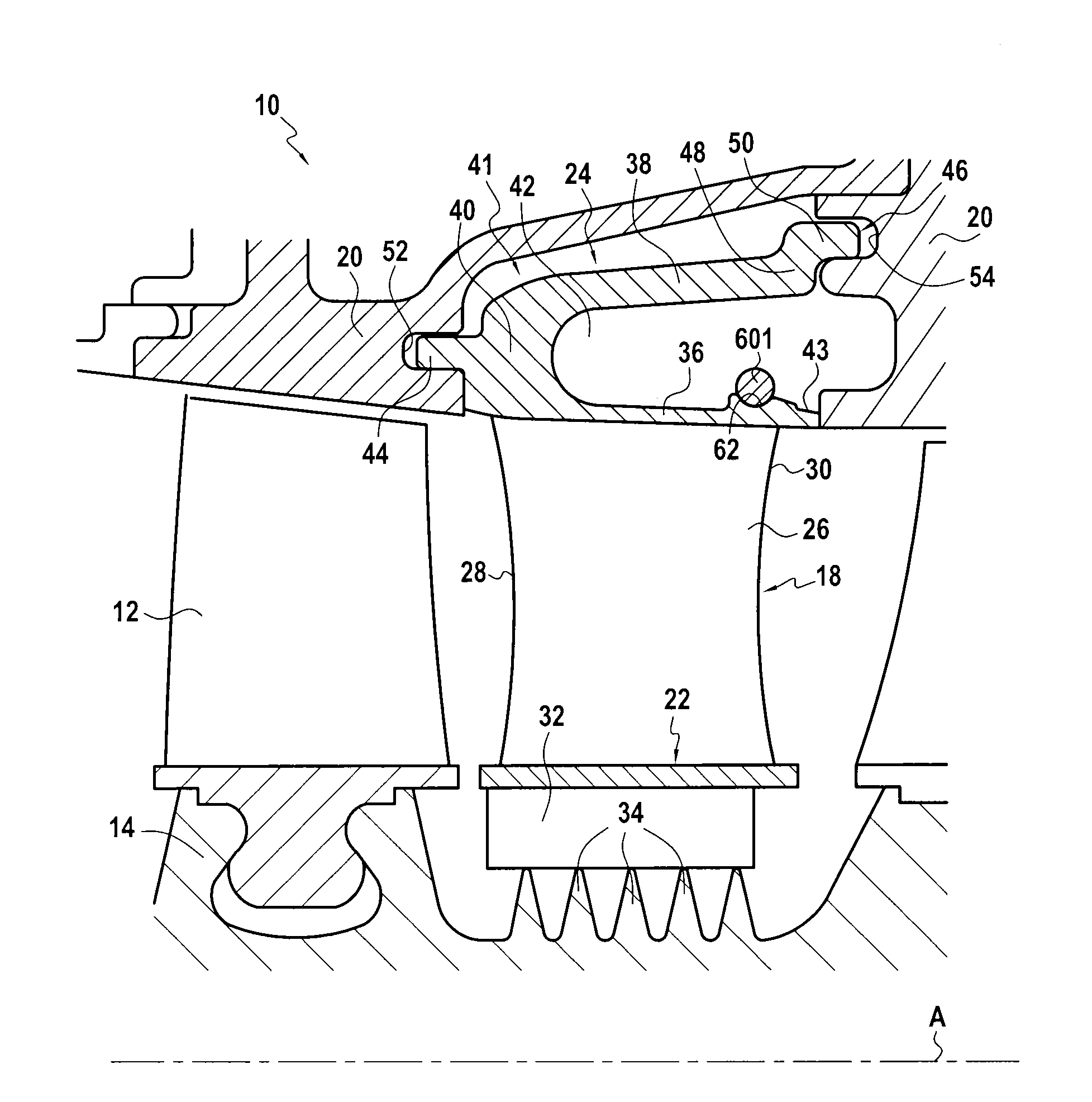
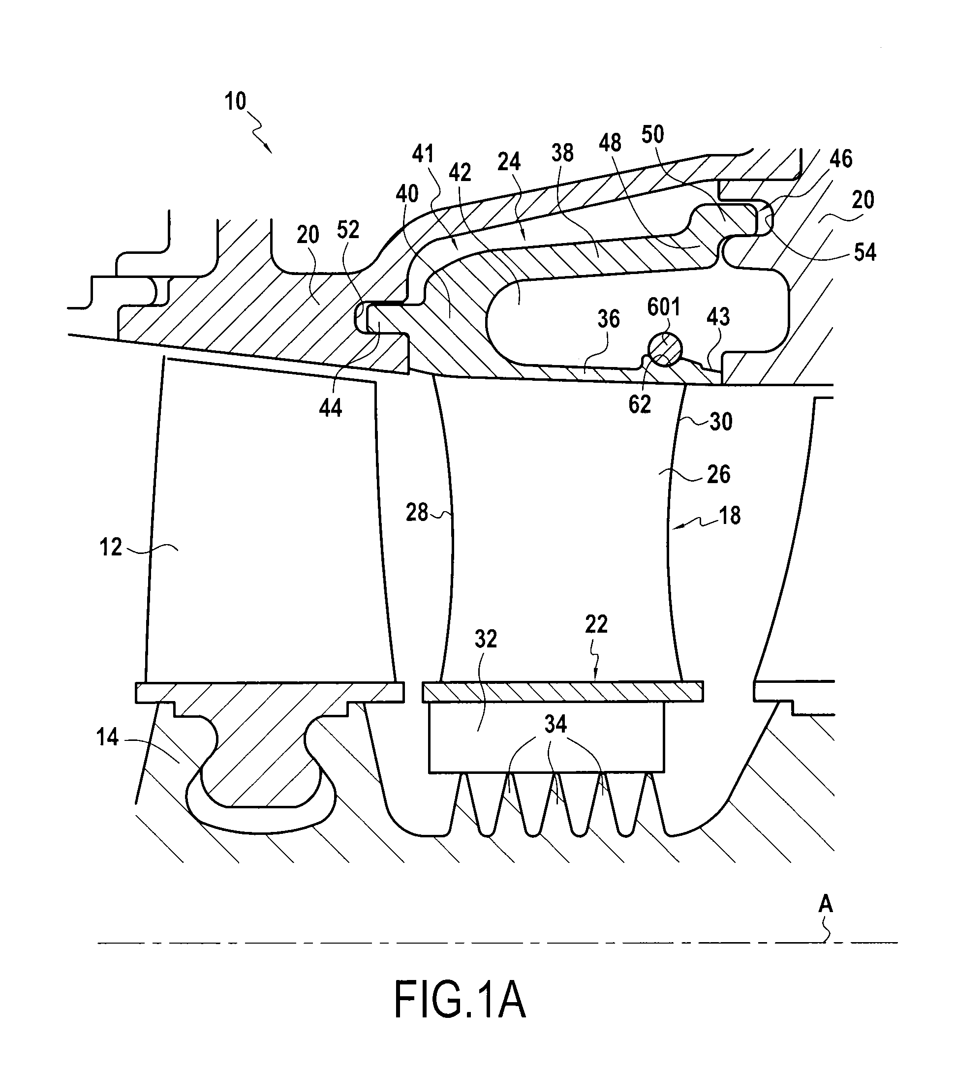
[0068]FIGS. 2A and 2B show the invention in which the damper insert is a portion 602 of a cylindrical ring having its inside surface pressed at rest against the outside face of the radially-inner tongue 36. Compared with the embodiments of FIGS. 1A and 1B, this shape serves to increase the bearing area between the damper insert and the radially-inner tongue 36.

[0069]All elements that are common with the embodiment of FIGS. 1A and 1B are given the same numerical references and are not described again for reasons of concision. The operation of the damper insert 602 is also identical to that described with reference to FIG. 1A.

[0070]In the example of FIG. 2A, a recess 62′ of shape complementary to that of the ring portion 602 is formed in the radially-inner tongue 36. This recess serves to hold the ring portion 602 axially once it is mounted in the cavity 42.

[0071]In an advantageous variant embodiment shown in FIG. 2B, provision may be made for the recess 62′ to open out to the downstr...

third embodiment

[0075]FIG. 3A shows the invention in which the damper insert is a resilient spring-forming clip 604 that is to bear against the radially-inner and radially-outer tongues 36 and 38 of the outer shroud 24 once inserted inside the cavity 42.

[0076]As can be seen in FIG. 3A, the clip 604 presents, in an axial plane, a section in the shape of a lower-case h with its vertical portion lying on the radially-inner tongue 36 of the outer shroud 24. More particularly, the clip 604 is a ring portion having a sleeve portion 71 and a hook portion 73 extending from said sleeve portion 71 in a radially outward direction and then towards the open end of the cavity 42. The sleeve portion 71 and the hook portion 73 form a spring that bears radially against the radially-inner tongue 36 and the radially-outer tongue 38 of the outer shroud 24 with a weak clamping force. The flexibility of the clip 604 needs to be optimized in order to obtain good contact with the radially-inner and -outer tongues, while m...

fourth embodiment

[0097]A fourth embodiment is described below with reference to FIG. 4.

[0098]In this embodiment, the damper insert is a clip 605 having the same structure as the clip 604 described with reference to FIGS. 3A and 3B. In particular it likewise presents in an axial plane a section that is in the shape of a lower-case h with the vertical portion thereof lying on the radially-inner tongue 36 of the outer shroud 24. It is therefore not described again in detail.

[0099]This fourth embodiment differs from that of FIGS. 3A and 3B solely in that the radially-outer tongue 38 carries a projection 86 directly radially towards the inside of the cavity 42, thereby forming an axial retention stop for the damper insert in the form of a clip 605.

[0100]Thus, the end of the hook portion 73 bears both radially against the radially-outer tongue 38 and, via its downstream end face 84, axially against the retention stop 86.

[0101]The clip 605 is thus held axially inside the cavity 42 of the outer shroud 24 an...


PUM


Abstract

A stator angular sector for a turbine engine compressor including: an outer shroud and an inner shroud, and at least one vane extending radially between the shrouds. The outer shroud includes first and second mounting mechanisms for mounting the stator angular sector on a casing of the engine, which mechanisms are oriented parallel to the axis in opposite directions and connected together by an intermediate portion. The outer shroud includes at least one axial end portion extending from the intermediate portion with which at least one damper-forming insert is configured to come into contact, such that beyond a given value for amplitude of vibration of the end portion, the damper insert and the end portion are configured to move relative to each other to vary total moving mass moving with the end portion, thereby modifying vibratory behavior of the end portion.

Description

BACKGROUND OF THE INVENTION[0001]The present invention relates to the general field of stators for a compressor in a turbine engine such as an airplane turboprop or turbojet.[0002]A compressor in a turbine engine is made up of a plurality of compression stages, each comprising both an annular row of moving blades mounted on a shaft of the engine, and also a stator mounted on an outer annular casing of the engine.[0003]A compressor stator may be constituted by a ring, or it may be sectorized (i.e. made up of a plurality of angular sectors connected circumferentially end to end around the longitudinal axis of the compressor). Throughout the present application, the term “stator angular sector” (or “stator sector” to be more concise) is used to mean any angular sector of a stator and presenting an angle that is less than or equal to 360°.[0004]Each stator sector has an outer shroud and an inner shroud that are arranged coaxially one in the other, together with one (or more) vane(s) ext...

Claims


Application Information

Patent Timeline
Patent Type & Authority Applications(United States)
IPC IPC(8): F01D25/04
CPCF01D5/26F01D9/042F01D25/246F01D25/04Y02T50/671F05D2240/80F05D2260/96F05D2260/38F04D29/542F04D29/668Y02T50/60F01D25/06F01D5/225
Inventor CLOAREC, YVON
Owner SN DETUDE & DE CONSTR DE MOTEURS DAVIATION S N E C M A
Why Eureka
Try Eureka