
Numerical control machine

Active Publication Date: 2013-08-29
OKUMA CORP
View PDF5 Cites 7 Cited by
  • Summary
  • Abstract
  • Description
  • Claims
  • Application Information

AI Technical Summary

Benefits of technology

The invention aims to minimize fluctuations in cutting feed amount per rotation of the main spindle during cutting processing. This is achieved by reducing the difference between the rotational speed fluctuations of the main spindle and the feed rate fluctuations during processing. This helps to suppress chattering vibrations, which can lead to stripes on the processed surface and reduced quality of finished surfaces.

Problems solved by technology

In cutting processing, non-uniform cutting surfaces are caused unless the cutting feeding amount per one rotation of a main spindle is kept constant.

Method used


Image

  • Numerical control machine
  • Numerical control machine
  • Numerical control machine

Examples


Embodiment Construction

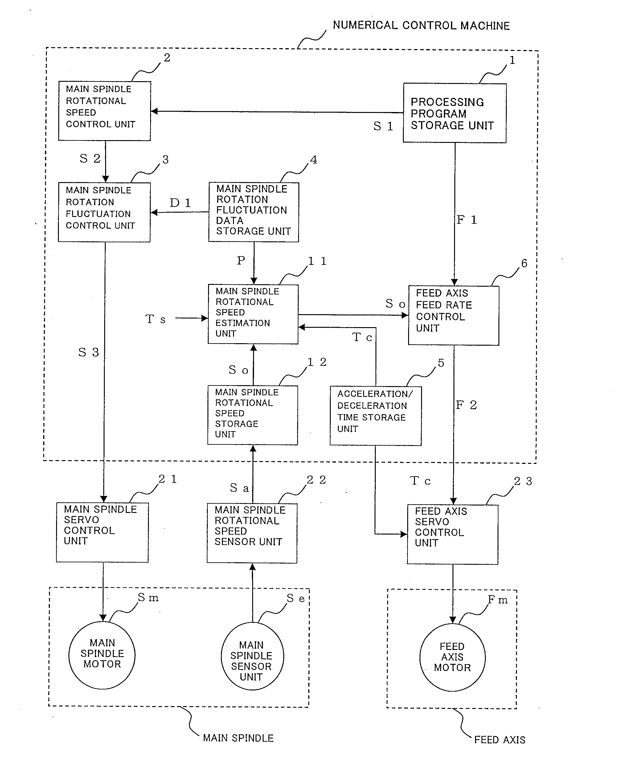
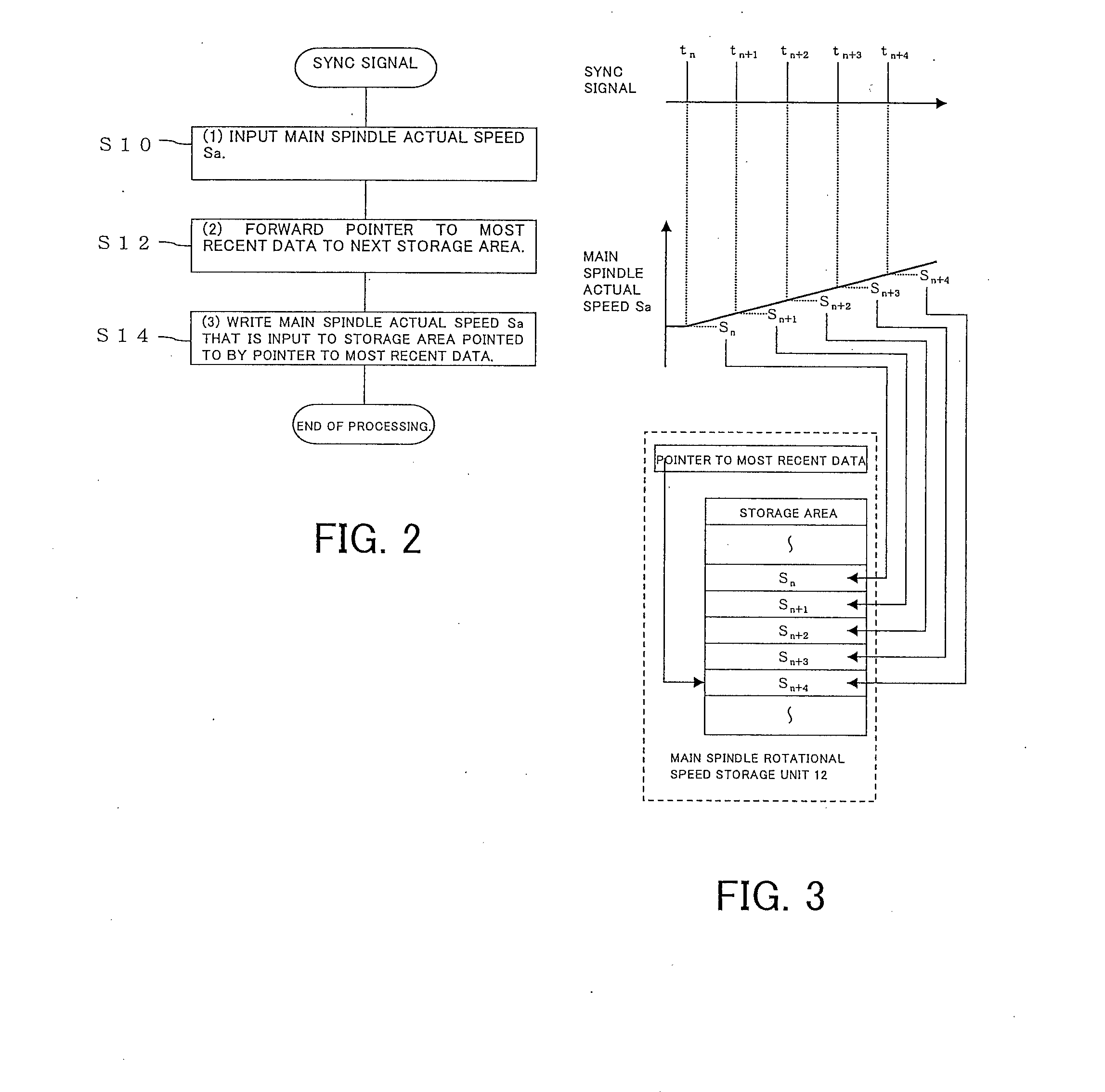
[0024]Embodiments according to the present invention are described below by referring to the drawings. FIG. 1 is a block diagram showing a configuration of a numerical control machine according to one embodiment of the present invention.

[0025]First, operations of a main spindle are described. A main spindle rotational speed program command S1 which is read from a processing program storage unit 1 is input to a main spindle rotational speed control unit 2. In the main spindle rotational speed control unit 2, various arithmetic processes are performed on the main spindle rotational speed program command S1 to calculate and output a main spindle rotational speed command S2. These various arithmetic processes include, for example, arranging the rotational speed within an allowable range in accordance with a current main spindle gear range conditions when a multi-stage main spindle gear range is used, with an override switch disposed externally, multiplying magnification in accordance wi...


PUM


Abstract

A numerical control machine estimates a future rotational speed ahead by a delay time that is a phase difference between a rotational speed fluctuation of a main spindle and a feed rate fluctuation of a feed axis, and fluctuates the feed rate such that a constant ratio is maintained with the estimated rotational speed.

Description

PRIORITY INFORMATION[0001]This application claims priority to Japanese Patent Application No. 2012-37442, filed on Feb. 23, 2012, which is incorporated herein by reference in its entirety.BACKGROUND[0002]1. Technical Field[0003]The present invention relates to a numerical control machine including a vibration suppressing unit that fluctuates, in a predetermined fluctuation cycle, a commanded rotational speed of a main spindle based on pre-stored main spindle fluctuation data including the fluctuation cycle, and also fluctuates a feed rate of a feed axis while maintaining a constant ratio between the feed rate of the feed axis and the rotational speed of the main spindle.[0004]2. Related Art[0005]As a method for suppressing chattering vibrations in cutting processing, a method disclosed in JP 49-105277 A is known. This method suppresses chattering vibrations by fluctuating the rotational speed of a main spindle during cutting processing with a preset fluctuation amplitude and fluctua...

Claims


Application Information

Patent Timeline
IPC IPC(8): G05B19/18
CPCG05B19/18G05B2219/49077G05B2219/43187G05B19/4166
Inventor UENO, SHIGEKI
Owner OKUMA CORP
Features
  • Generate Ideas
  • Intellectual Property
  • Life Sciences
  • Materials
  • Tech Scout
  • Unparalleled Data Quality
  • Higher Quality Content
  • 60% Fewer Hallucinations
Learn More