Charge and discharge control apparatus and method

a control apparatus and discharge control technology, applied in the direction of vehicle position/course/altitude control, process and machine control, instruments, etc., can solve the problems of difficult to improve the convergence properties, driver or passenger of the vehicle likely to feel uncomfortable, etc., to achieve the effect of quick convergence of the soc of the battery and increase the convergence properties

Active Publication Date: 2013-08-29
TOYOTA JIDOSHA KK
View PDF3 Cites 5 Cited by
  • Summary
  • Abstract
  • Description
  • Claims
  • Application Information

AI Technical Summary

Benefits of technology

[0011]Particularly in the present invention, the setting device sets the hunting allowable period. The “hunting allowable period” of the present invention is a hunting period (period of oscillation) in which the hunting of the engine power (i.e. oscillation of the engine power) is allowed, and is a hunting period that does not make a driver or passenger of the vehicle feel uncomfortable (i.e. that is allowed by the driver or passenger of the vehicle in terms of his or her senses) even through the hunting of the engine power occurs. In general, as the hunting period of the engine power becomes longer, the driver or passenger of the vehicle hardly feels uncomfortable, and as the hunting period of the engine power becomes shorter, the driver or passenger of the vehicle easily feels uncomfortable. The setting device sets, for example, the shortest hunting period, out of a relatively long range of the hunting period which does not make the driver or passenger of the vehicle feel uncomfortable, as the hunting allowable period. The hunting allowable period can be determined in advance on the basis of experiments, simulations, or the like. For example, the hunting allowable period determined in advance in this manner is stored in advance in a memory provided for the setting device. The setting device performs the setting by reading the hunting allowable period from the memory.
[0012]The calculating device calculates the charge and discharge amount of the battery by multiplying the difference between the SOC of the battery and the target SOC, by the charge and discharge coefficient determined on the basis of the hunting allowable period. In other words, the calculating device firstly determines the charge and discharge coefficient on the basis of the hunting allowable period. Here, the charge and discharge coefficient is an inclination (or proportionality constant) of the charge and discharge of the battery with respect to the difference between the SOC and the target SOC, and can be rephrased as a gain value when the charge and discharge amount of the battery is determined on the basis of the difference between the SOC and the target SOC. The calculating device calculates the charge and discharge coefficient by dividing a product between battery capacity and battery voltage of the battery by the hunting allowable period. The calculating device then calculates the charge and discharge amount of the battery by multiplying the difference between the SOC and the target SOC by the charge and discharge coefficient. Here, particularly in the present invention, the charge and discharge coefficient is determined on the basis of the hunting allowable period. Thus, the driver or passenger of the vehicle hardly feels uncomfortable or does not feel uncomfortable at all even if the hunting of the engine power occurs by controlling the charge and discharge of the battery on the basis of the calculated charge and discharge amount. Moreover, the calculating device can determine the charge and discharge coefficient to have, for example, a maximum value within a range in which the hunting of the engine power does not make the driver or passenger of the vehicle feel uncomfortable. Thus, the calculating device can calculate, for example, the maximum value within the range in which the driver or passenger of the vehicle does not have an uncomfortable feeling due to the hunting of the engine power. Therefore, it is possible to quickly make the SOC of the battery converge to the control center SOC (i.e. it is possible to increase convergence properties in which the SOC of the battery converges to the control center SOC), with hardly providing or without providing the driver or passenger of the vehicle with an uncomfortable feeling due to the hunting of the engine power.
[0013]As explained above, according to the charge and discharge control apparatus of the present invention, it is possible to quickly make the SOC of the battery converge to the control center SOC, with hardly making or without making the driver or passenger of the vehicle feel uncomfortable.

Problems solved by technology

However, for example, according to the technology disclosed in the aforementioned Patent document 1, there is such a technical problem that it is hard to improve convergence properties, which are to make the SOC converge to the target SOC, because an inclination of a charge and discharge amount with respect to a difference between the SOC and the target SOC is constant.
As a result, a driver or passenger of a vehicle likely feels uncomfortable due to the hunting.

Method used


Image

  • Charge and discharge control apparatus and method
  • Charge and discharge control apparatus and method
  • Charge and discharge control apparatus and method

Examples


first embodiment

[0034]A charge and discharge control apparatus in a first embodiment will be explained with reference to FIG. 1 to FIG. 3.

[0035]Firstly, with reference to FIG. 1, an explanation will be given to an entire configuration of a hybrid vehicle to which the charge and discharge control apparatus in the first embodiment is applied.

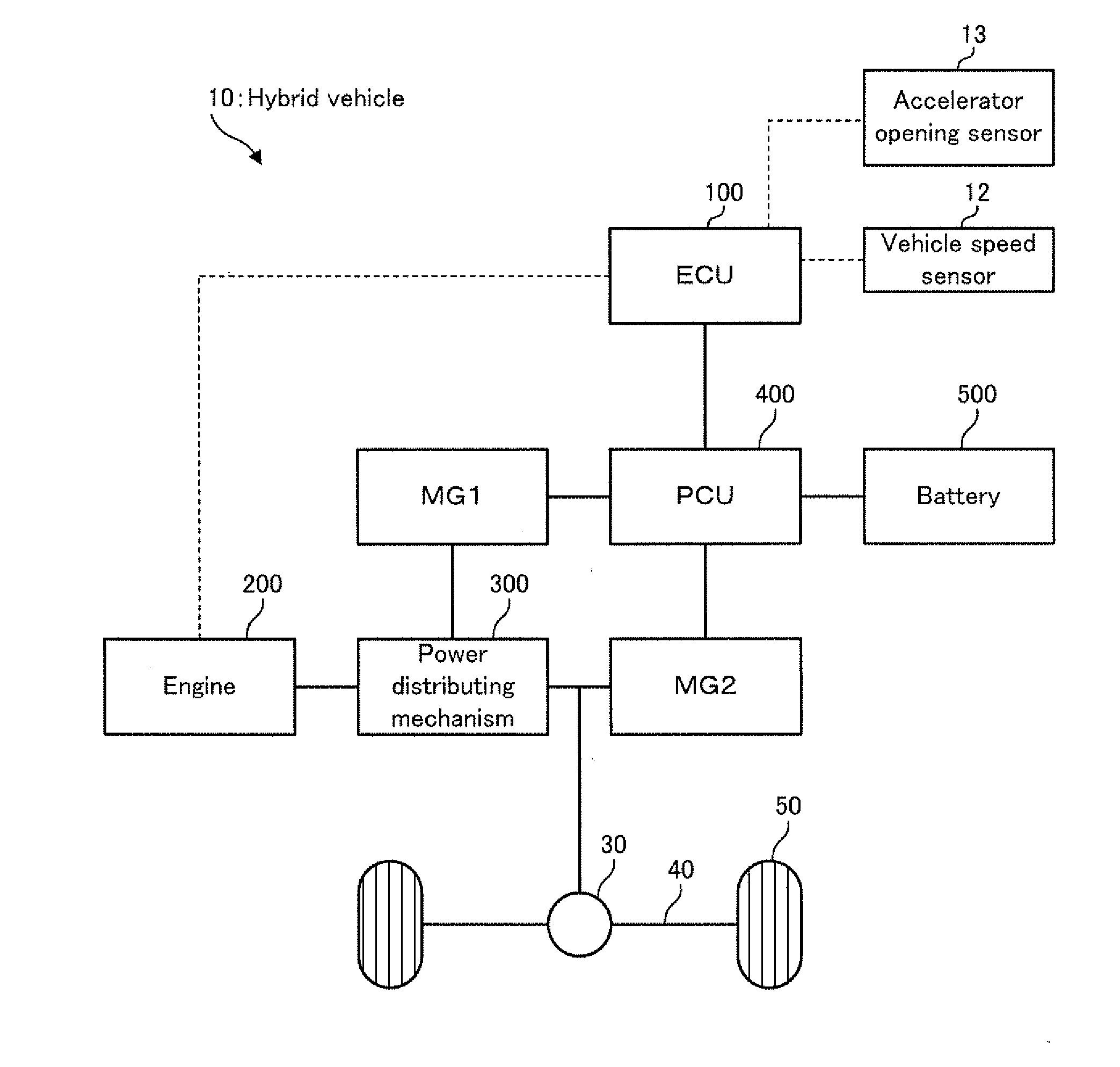
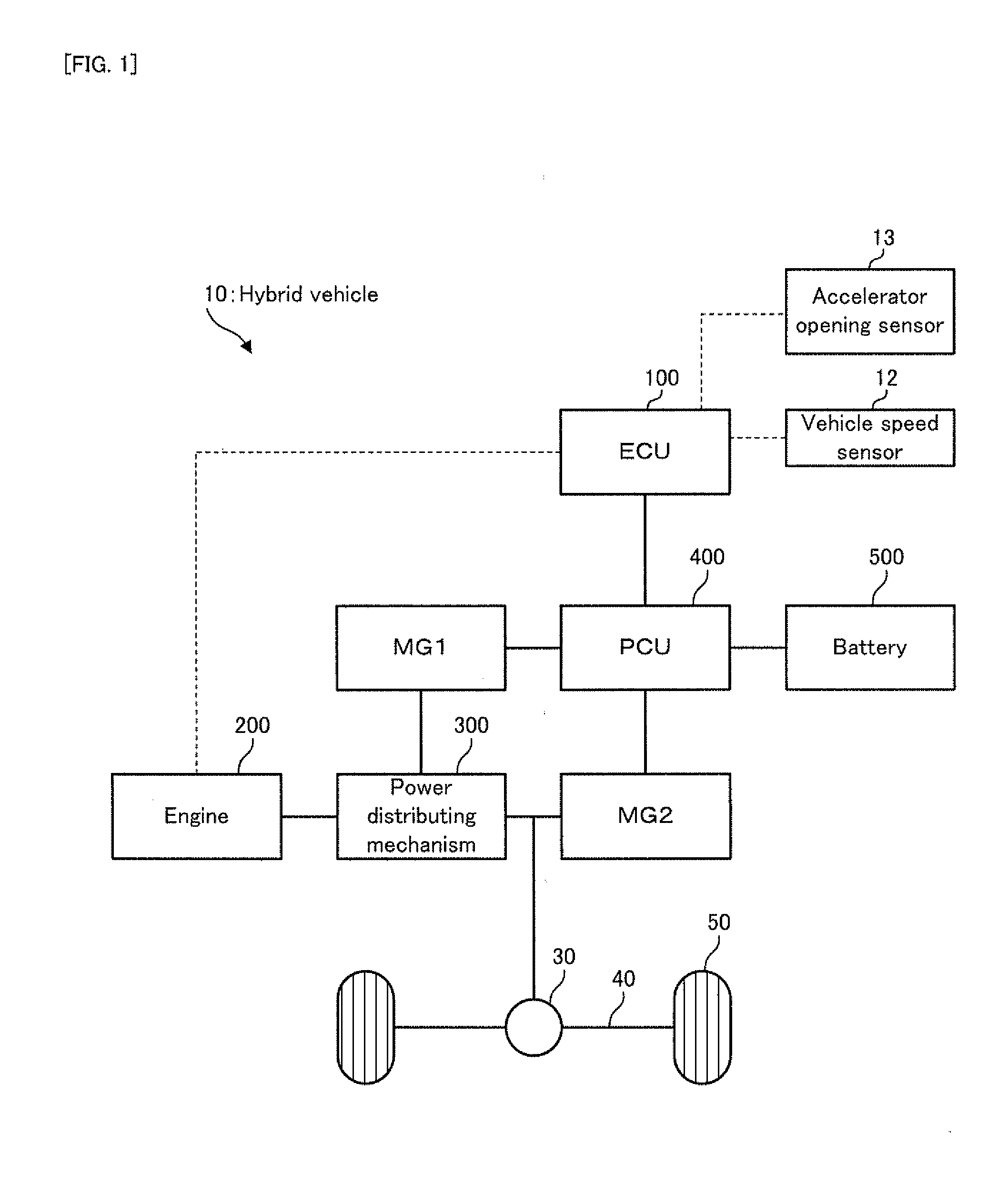
[0036]FIG. 1 is a schematic block diagram illustrating the configuration of the hybrid vehicle in the first embodiment.

[0037]In FIG. 1, a hybrid vehicle 10 in the first embodiment, which is one example of the “vehicle” of the present invention, is provided with an electronic control unit (ECU) 100, an engine 200, a motor generator MG1, a motor generator MG2, a power distributing mechanism 300, a power control unit (PCU) 400, a battery 500, a vehicle speed sensor 12, an accelerator opening sensor 13, a reduction gear mechanism (or speed reduction mechanism) 30, an axle 40, and wheels 50.

[0038]The ECU 100 is provided with a central processing unit (CPU), a read onl...

second embodiment

[0064]A charge and discharge control apparatus in a second embodiment will be explained with reference to FIG. 4 to FIG. 7.

[0065]FIG. 4 is a flowchart illustrating a flow of the charge and discharge control of the battery in the second embodiment. Incidentally, in FIG. 4, the same steps as those of the charge and discharge control of the battery in the first embodiment illustrated in FIG. 3 will carry the same step numbers, and the explanation thereof will be omitted as occasion demands.

[0066]In FIG. 4, the charge and discharge control of the battery in the second embodiment is different from the charge and discharge control in the first embodiment described above in that the hunting allowable period T is set on the basis of the driving state of the hybrid vehicle 10 (refer to steps S11 and S12), and is substantially the same as the charge and discharge control in the first embodiment described above in other points.

[0067]In FIG. 4, in the charge and discharge control of the battery...


PUM


Abstract

A charge and discharge control apparatus is provided with: a setting device which is configured to set a hunting allowable period (T), which is a hunting period in which hunting of engine power is allowed; and a calculating device which is configured to calculate a charge and discharge amount of a battery by multiplying a difference between a state of charge (SOC) of the battery and a target SOC, which is a target value of the SOC, by a charge and discharge coefficient determined on the basis of the hunting allowable period.

Description

TECHNICAL FIELD[0001]The present invention relates to a charge and discharge control apparatus and a charge and discharge control method, which are configured to control the charge and discharge of a battery mounted on a vehicle, such as, for example, a hybrid vehicle.BACKGROUND ART[0002]As this type of apparatus, there is known an apparatus which is mounted on a hybrid vehicle provided with a generator for generating electricity using engine power, and a battery (a storage battery) charged by the generator, and which is configured to control the charge and discharge of the battery such that a state of charge (SOC) of the battery is a target SOC (e.g. refer to Patent documents 1 and 2).[0003]For example, Patent document 1 discloses that a used area of the SOC of a battery is expanded and the battery is efficiently used by changing the target SOC, as occasion demands, on the basis of an average charge and discharge amount of the battery. For example, Patent document 2 discloses that ...

Claims


Application Information

Patent Timeline
Patent Type & Authority Applications(United States)
IPC IPC(8): B60W20/00B60W10/08B60W10/06B60L50/16
CPCB60K6/445B60W10/06B60W10/08B60W10/26Y10S903/93B60W2510/244Y02T10/6239Y02T10/6286B60W20/00Y02T10/62B60W20/30
Inventor KAWAI, TAKASHI
Owner TOYOTA JIDOSHA KK
Why Eureka
Try Eureka