Wiper lever assembly and wiper blade

a technology of lever assembly and wiper blade, which is applied in the direction of vehicle maintenance, vehicle cleaning, domestic applications, etc., can solve the problems of end cover member detachment and claw disengagemen

Active Publication Date: 2013-09-05
DENSO CORP +2
View PDF2 Cites 4 Cited by
  • Summary
  • Abstract
  • Description
  • Claims
  • Application Information

AI Technical Summary

Benefits of technology

[0007]Accordingly, the present invention has been made keeping in mind the above problems occurring in the prior art, and an object of the present invention is to provide a wiper lever assembly and a wiper blade which are configured to prevent the detachment of end cover members.
[0009]According to the first aspect, since the support wall of the end cover member is fitted in the receptor of the lever member from above, when a piece of snow obstructs the longitudinal end (outer end) of the end cover member thus applying a lateral load to the longitudinal end during wiping action, the support wall and the receptor can now accommodate the load. As a result, the action applied to the claws is mitigated, thus preventing the disengagement of the claws and thus the detachment of the end cover member.
[0011]According to the second aspect, since the support walls are disposed at two positions on the end cover member longitudinally spaced apart from each other, the load locally applied to the support walls can be reduced. In comparison, when the support walls are provided at a single position, the strength of the support walls can be more easily assured, and the support walls can as a result be made slimmer. Furthermore, although the load applied to the longitudinal end of the support wall is reduced by increasing the longitudinal length of the single support wall, the second lever may require a corresponding receptor which has a larger length, thus deteriorating strength of the lever member. In contrast, according to exemplary embodiment of the present invention, the receptors may be provided to correspond to the respective support walls and thus the lever member does not require the longer corresponding receptor as a result. This improves the overall strength of the lever member.
[0013]According to the third aspect, the claws are provided at two positions on the end cover member longitudinally spaced apart from each other, and the claws disposed at a position near the longitudinal end of the lever member are formed to have a width that is larger than that of the claws disposed at a position near the longitudinal center of the lever member. Consequently, in comparison to when the claws are modified into a single longer claw without spacing, this aspect can reduce the consumption of materials and can improve the strength of the claws and thus improve resistance to a force which is applied to lift the longitudinal end (outer end) of the end cover member. More specifically, when the longitudinal end (outer end) of the end cover member is intended to be lifted while the rubber blade is firmly sticking to a wiping surface due to freezing, the claws disposed at a position near the longitudinal end of the lever member may be provided with a load that is greater than that applied to the claws disposed at the position near the longitudinal center of the lever member. Consequently, this aspect can optimize the strength of the claws.
[0015]According to the fourth aspect, since each movement-suppressing protrusion is formed at a position upwardly spaced apart from the claw, there is no perpendicular contact of the upper proximal portion of the claw with respect to the movement-suppressing protrusion. Furthermore, because the round corner having a round transverse section is provided between the proximal end of the claw and the inner surface of the end cover member, it is possible to prevent stress concentration on the proximal end of the claw and to assure the desirable strength of the claw.
[0017]According to the fifth aspect, since the claw disposed at the longitudinal end of the lever member engages at the center area in a claw width direction with the outmost end of a bottom edge of the lever member, the center area of the claw can accommodate force which is applied to lift the longitudinal end (the outer end) of the end cover member, thus providing the desirable strength of the claw.

Problems solved by technology

However, when the end cover members which cover longitudinal ends of the lever member are mounted on just the lever member by the engagement of claws thereof with the lever member, and when a lateral load is applied to the end cover member during a wiping action, such as when a piece of snow obstructs the longitudinal end of the end cover member, the claws can be disengaged and in some cases the end cover member may detach.

Method used


Image

  • Wiper lever assembly and wiper blade
  • Wiper lever assembly and wiper blade
  • Wiper lever assembly and wiper blade

Examples


Embodiment Construction

[0047]It is understood that the term “vehicle” or “vehicular” or other similar term as used herein is inclusive of motor vehicles in general such as passenger automobiles including sports utility vehicles (SUV), buses, trucks, various commercial vehicles, watercraft including a variety of boats and ships, aircraft, and the like, and includes hybrid vehicles, electric vehicles, combustion, plug-in hybrid electric vehicles, hydrogen-powered vehicles and other alternative fuel vehicles (e.g. fuels derived from resources other than petroleum).

[0048]Hereinafter, a preferred embodiment of the present invention will be described in detail with reference to FIGS. 1 to 8.

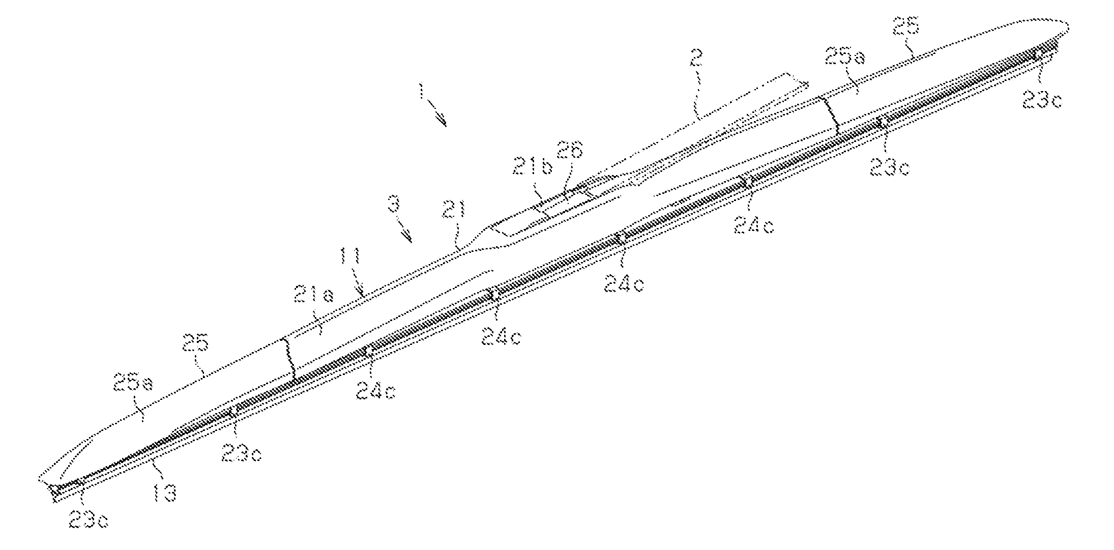
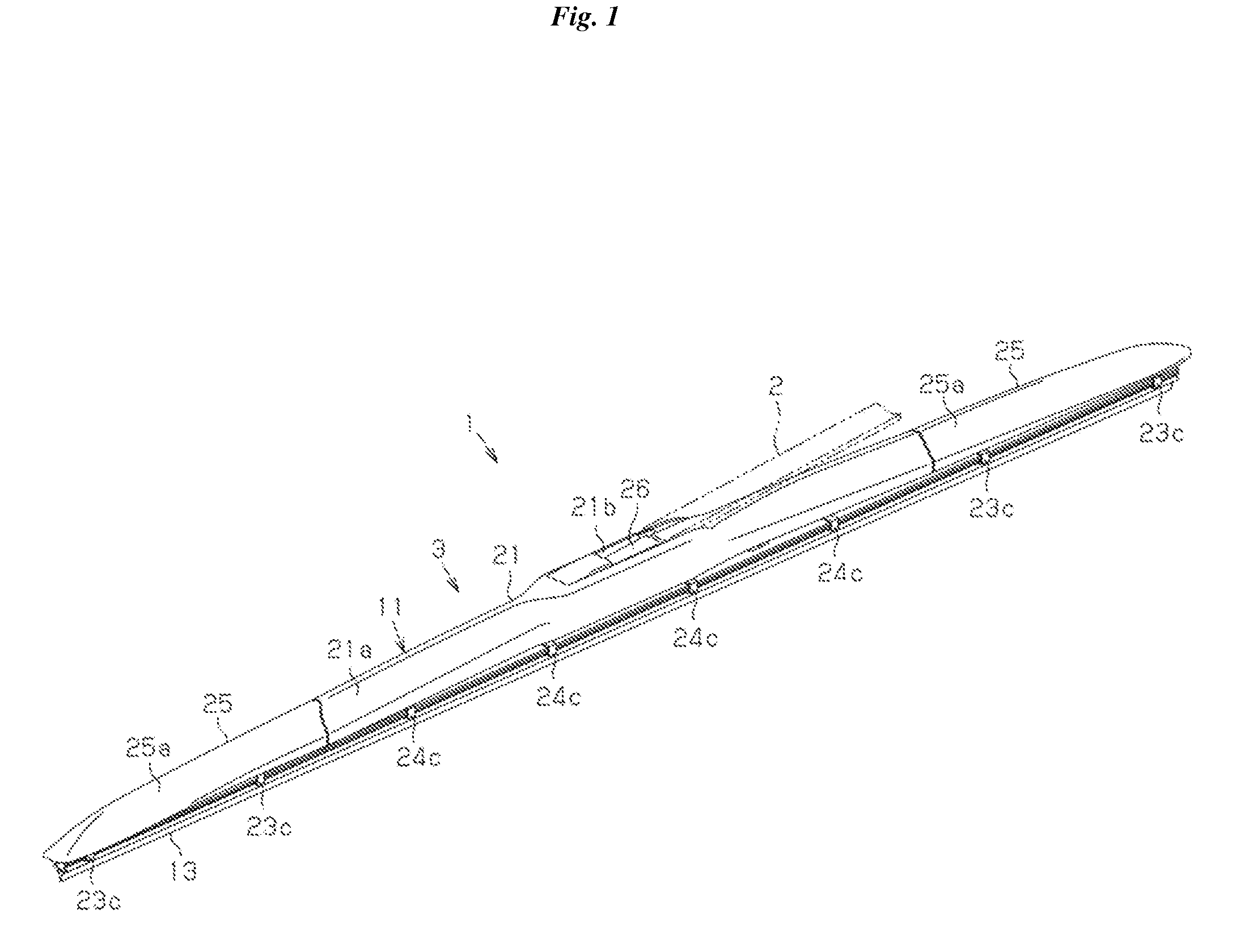
[0049]As shown in FIG. 1, an vehicle wiper 1 according to an exemplary embodiment of the present invention, which is configured to wipe away substances adhering to a wiping surface of a windshield of an vehicle, includes a wiper aim 2, and a wiper blade 3 coupled to the wiper arm 2. The wiper aim 2 has a proximal end fixed t...


PUM


Abstract

Disclosed herein is a wiper lever assembly which is configured to prevent detachment of end cover members, which includes a lever member (a center cover lever, secondary levers and yoke levers) gripping a rubber blade disposed thereunder, and an end cover member which covers an end of the lever member from above and which includes claws formed on both lateral sides thereof. The claws may be extended inwardly from the end cover and engage with both lateral sides of a lower surface of the lever member to grip the lever member. The end cover member includes a support wall which is formed at the center of a width of the end cover member and is extended downwardly therefrom, and the lever member includes a receptor (an insert tube and a proximal insert tube) in which the support wall is fitted from above.

Description

BACKGROUND OF THE INVENTION[0001]1. Field of the Invention[0002]The present invention relates to a wiper lever assembly and wiper blade.[0003]2. Description of the Related Art[0004]Among conventional wiper blades, a particular wiper blade is known which includes a lever member that includes an upper lever, with a lower lever coupled to the upper lever so that the longitudinal center of the lower lever is pivotally connected to a longitudinal end of the upper lever to configure a tournament shape, a rubber blade disposed beneath and gripped by the lever member, and a cover member which covers the lever member from above. The cover member of the wiper blade is provided at both lateral sides thereof with claws which extend inwardly toward each other and engage with both lateral sides of a lower surface of the lever member in order to grip the lever member, thus enabling the cover member to be mounted on the lever member.[0005]When a lever member includes levers coupled to each other in...

Claims


Application Information

Patent Timeline
Patent Type & Authority Applications(United States)
IPC IPC(8): B60S1/34
CPCB60S1/3801B60S1/34B60S2001/3815B60S1/38B60S1/3806B60S2001/3843
Inventor LEE, KI YOUNGLEE, DONG SOOLEE, IN KWANGCHA, IN GUELEE, HEUI GEONAMANO, SHINICHIROU
Owner DENSO CORP
Why Eureka
Try Eureka