Parking brake in a vehicle

a technology for parking brakes and vehicles, applied in mechanical equipment, brake systems, transportation and packaging, etc., can solve the problems of adding to the electromechanically generated clamping force, and adding to the clamping for

Inactive Publication Date: 2013-09-05
ROBERT BOSCH GMBH
View PDF14 Cites 14 Cited by
  • Summary
  • Abstract
  • Description
  • Claims
  • Application Information

AI Technical Summary

Benefits of technology

[0017]To prevent a false polarity, a polarity reversal protection is adva...

Problems solved by technology

Basically, the hydraulic pressure of the vehicle brake may also be active when the vehicle is at a standstill and ma...

Method used


Image

  • Parking brake in a vehicle
  • Parking brake in a vehicle
  • Parking brake in a vehicle

Examples


Embodiment Construction

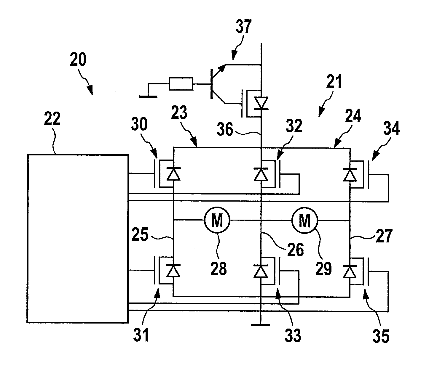
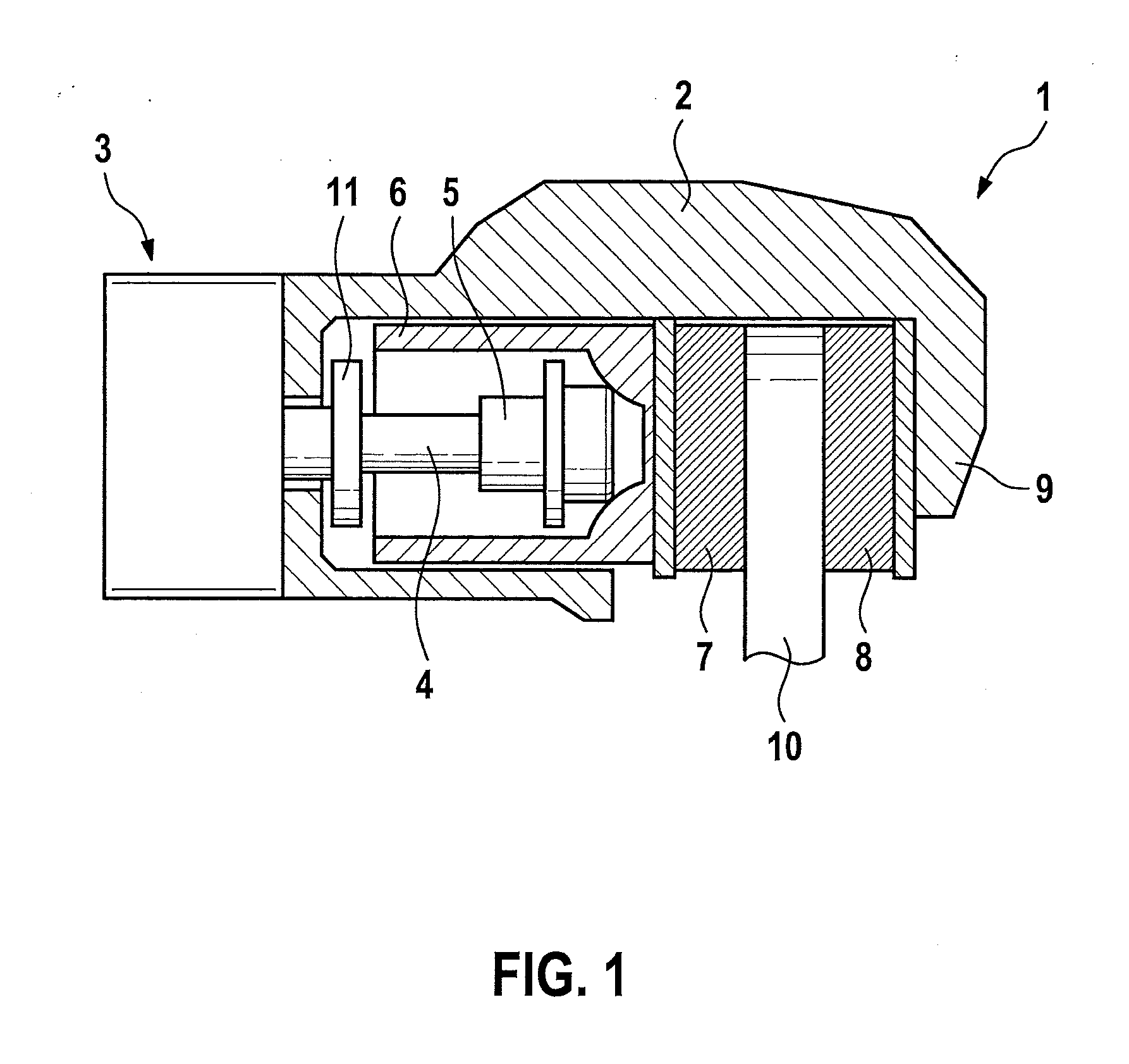
[0021]FIG. 1 shows an electromechanical parking brake 1 in a vehicle, a clamping force which holds the vehicle at a standstill being generatable via the parking brake. Parking brake 1 has a brake caliper 2 having a caliper unit 9 which reaches over brake disk 10. A brake motor 3 which is designed as an electric motor and which rotatingly drives a spindle 4, on which a spindle component 5 is displaceably installed, is used as the final control element of parking brake 1. Spindle component 5 is axially displaced when spindle 4 rotates. Spindle component 5 moves within a brake piston 6, which is the carrier of a brake lining 7 which is pressed by brake piston 6 against brake disk 10. Another brake lining 8, which is held in a fixed position on caliper unit 9, is situated on the opposite side of brake disk 10.

[0022]Within brake piston 6, spindle component 5 is able to move axially forward in the direction of the brake disk when spindle 4 rotates, and it is able to move axially rearward ...


PUM


Abstract

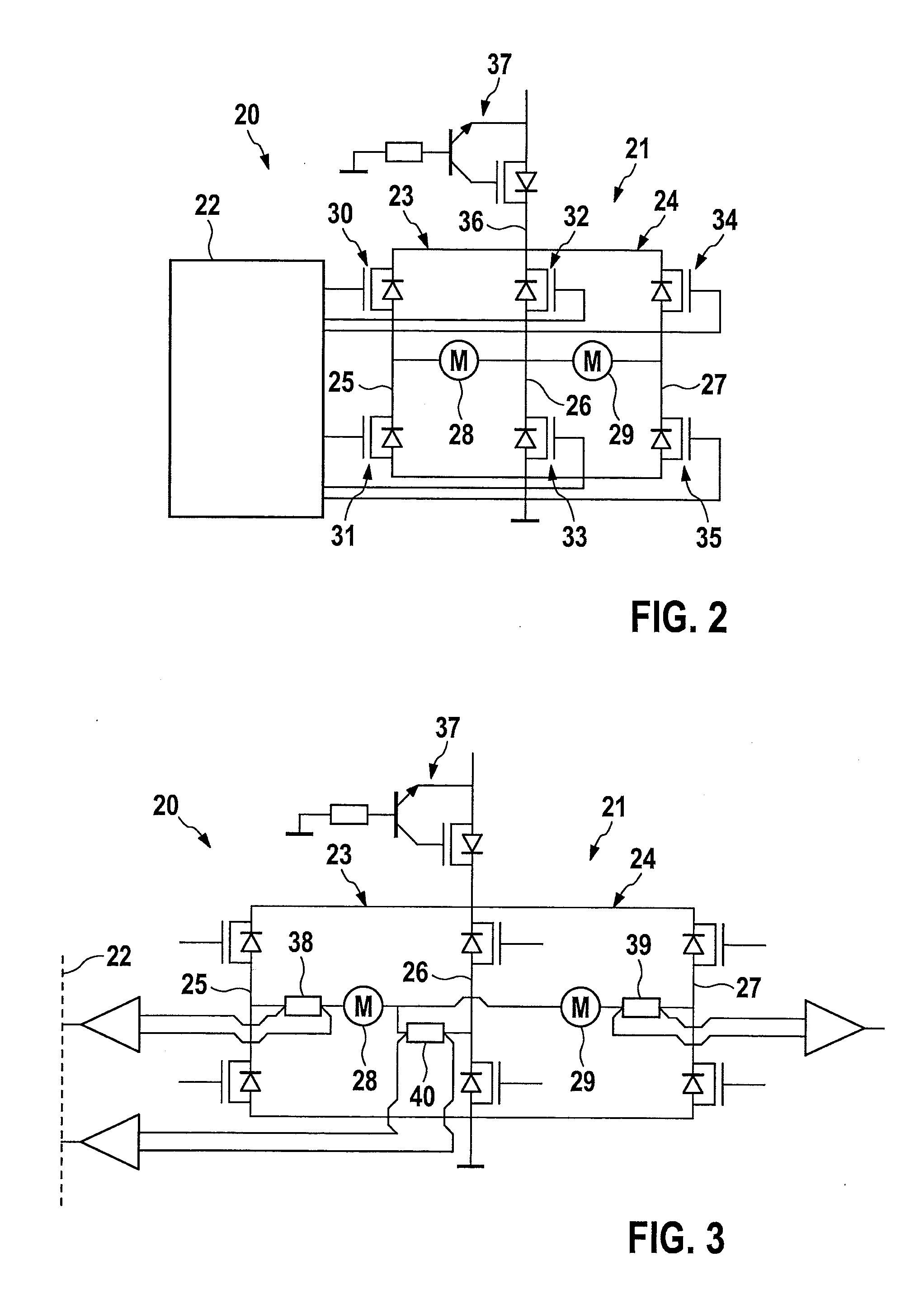
A parking brake in a vehicle has one wheel-brake unit on each of two vehicle wheels, each having one DC brake motor for generating a clamping force which holds the vehicle at a standstill. The electric brake motors are controllable via a control unit, each brake motor being assigned one H-bridge and the H-bridges being interconnected in such a way that one shared half-bridge branch having switches for controlling both brake motors is formed.

Description

BACKGROUND OF THE INVENTION[0001]1. Field of the Invention[0002]The present invention relates to a parking brake in a vehicle.[0003]2. Description of the Related Art[0004]Electromechanical parking brakes are known for generating a clamping force which holds the vehicle at a standstill with the aid of an electric brake motor. When the brake motor is activated, a brake piston, which is the carrier of a brake lining, presses against a brake disk. Such a parking brake is known from German patent document DE 103 61 042 B3, for example.[0005]The parking brake usually acts upon the wheel brake units of both wheels of the rear axle, each wheel brake unit being assigned an electric brake motor for generating the desirable clamping force. During the engagement process for building up the clamping force, the electric brake motors are controlled via an assigned control electronics in one direction, and for releasing the clamping force, the brake motors are controlled in the opposite direction. ...

Claims


Application Information

Patent Timeline
IPC IPC(8): B60T13/74B60T1/06
CPCF16D55/226F16D65/183F16D2121/04B60T13/741F16D2123/00B60T1/065B60T13/74F16D2121/24B60T7/045B60T7/107B60T13/746
Inventor LEIBFRIED, OLIVERPAESSLER, ALEXANDER
Owner ROBERT BOSCH GMBH
Why Eureka
Try Eureka