projector
a projector and projector technology, applied in the field of projectors, can solve the problems of reducing the quality of the displayed image, the intensity unevenness of the light exiting the polarization conversion element, etc., and achieve the effects of reducing the degree of intensity unevenness of light, excellent image display quality, and reducing the unevenness of illumination
- Summary
- Abstract
- Description
- Claims
- Application Information
AI Technical Summary
Benefits of technology
Problems solved by technology
Method used
Image
Examples
first embodiment
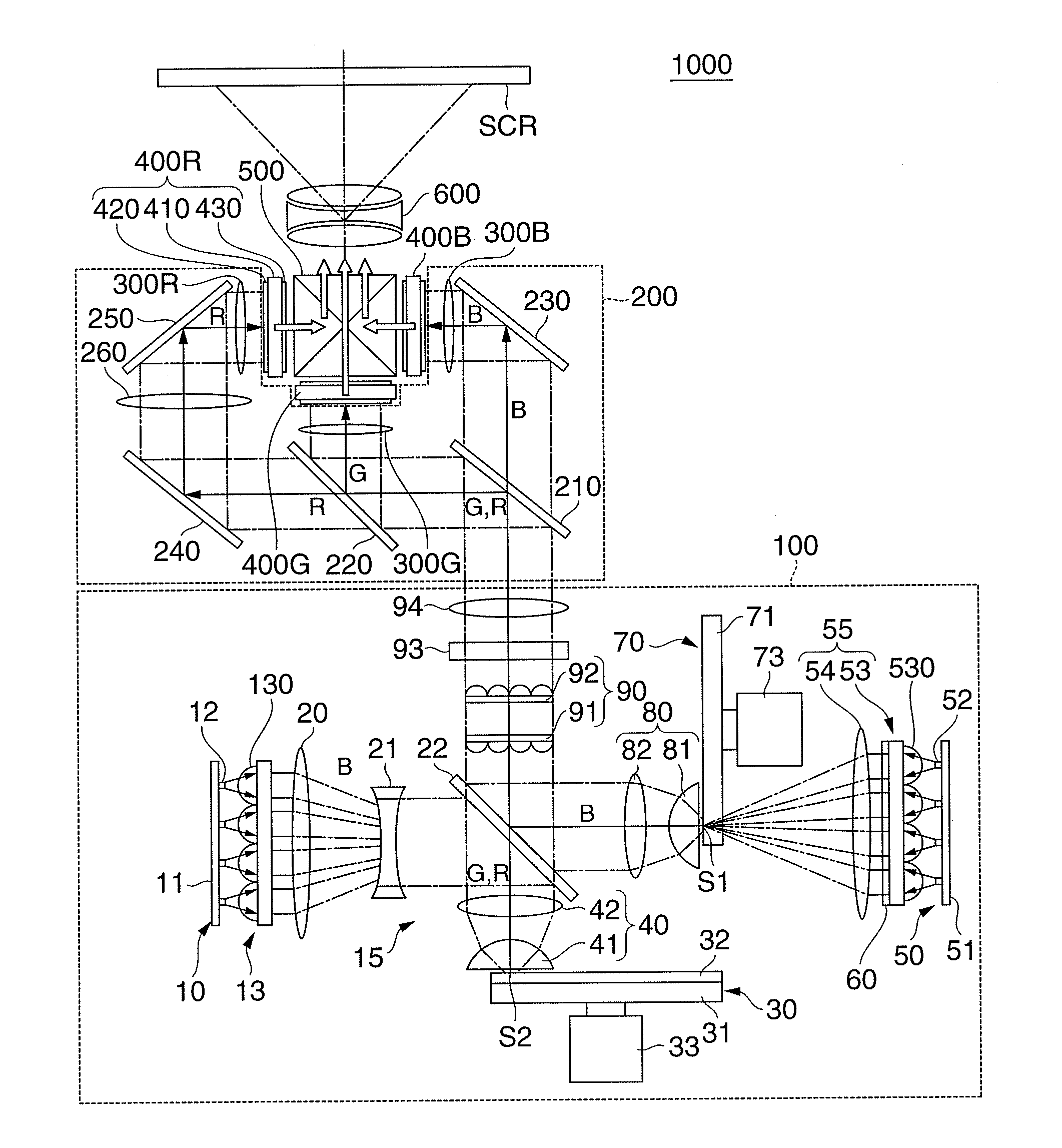
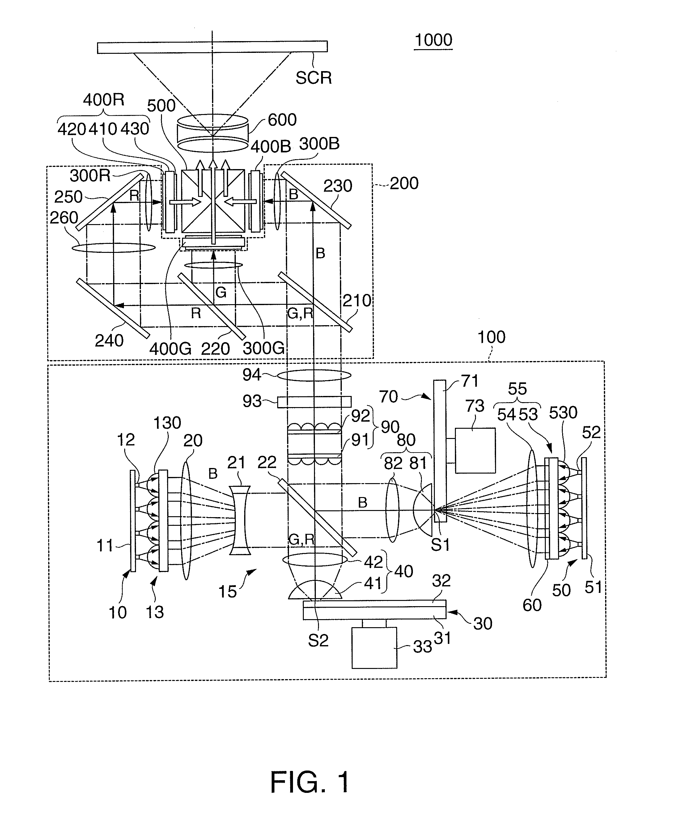
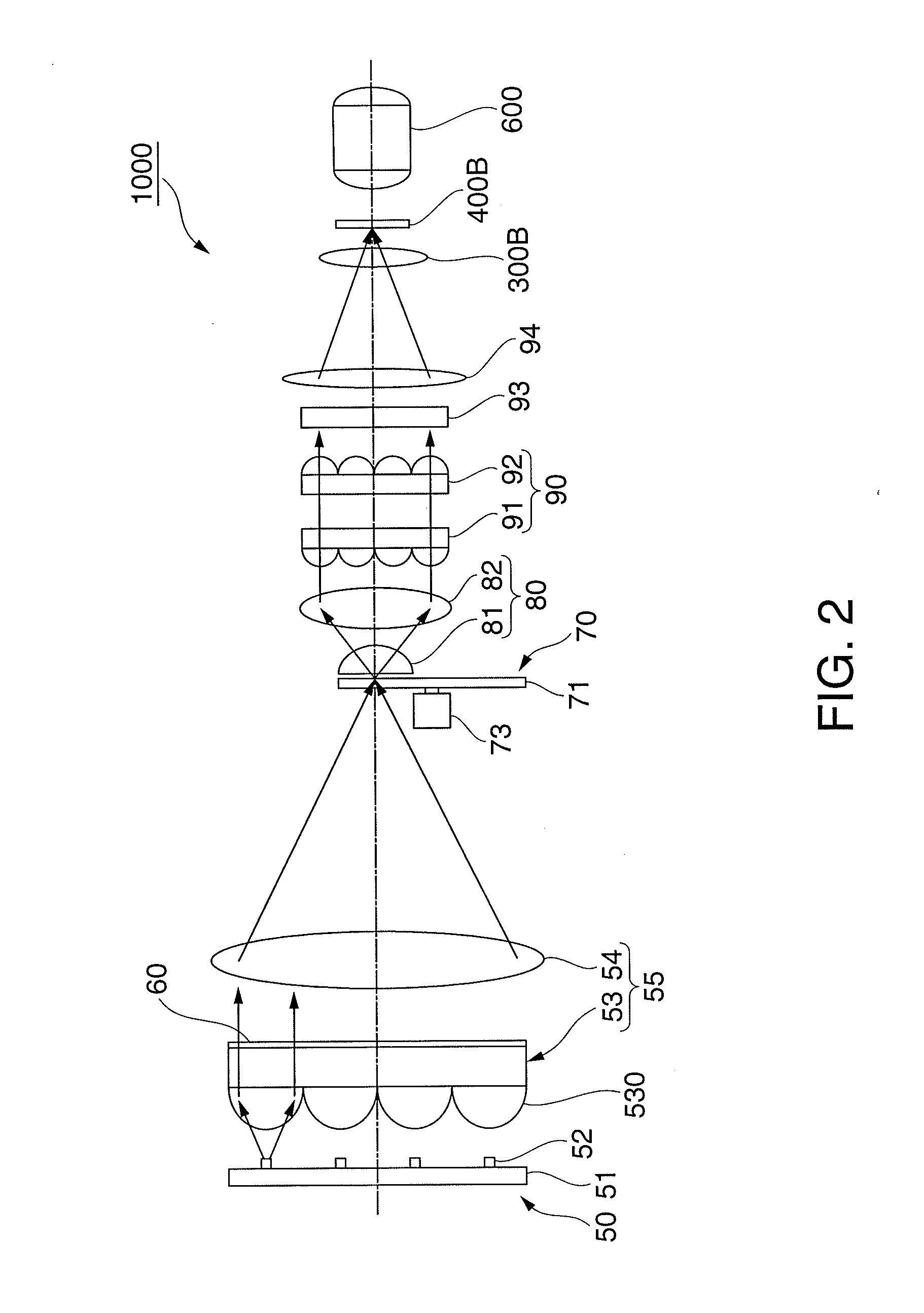
[0044]A projector according to an embodiment of the invention will be described with reference to FIGS. 1, 2, 3A to 3C, 4A and 4B, and 5A to 5C.
[0045]In the present embodiment, a projector 1000 will be described with reference to a projection-type projector that projects color light containing image information and produced by light modulation devices through a projection system on a screen (surface on which light is projected).
[0046]FIG. 1 is a pattern diagram showing the optical system of the projector 1000 according to the first embodiment of the invention. FIG. 2 is a schematic view showing the optical system of the projector 1000. In FIG. 2, a second light source array 10, a dichroic mirror 22, and other members are omitted for convenience.
[0047]The projector 1000 includes an illuminator 100, a color separation / light guiding system 200, liquid crystal light modulators 400R, 400G, and 400B as light modulators, a cross dichroic prism 500, and a projection system 600, as shown in ...
second embodiment
[0137]FIG. 6 is a schematic view corresponding to FIG. 2 and showing the optical system of a projector 1001 according to a second embodiment of the invention.
[0138]The projector 1001 according to the present embodiment differs from the projector 1000 according to the first embodiment described above in that a λ / 2 plate 61 as the birefringence element is disposed in the optical path between the rotating diffuser plate 70 and the polarization conversion element 93, as shown in FIG. 6. The λ / 2 plate 61 is so set that the direction of the optic axis thereof is inclined by an angle greater than or equal to −45° but smaller than or equal to +45° (22.5°, for example) to the polarization direction of linearly polarized light emitted from the first solid-state light sources 52 and incident on the λ / 2 plate 61 without undergoing the depolarization in the rotating diffuser plate 70. The other points are the same as those in the configuration described above. The same elements as those in FIG. ...
third embodiment
[0145]FIG. 7 is a schematic view corresponding to FIG. 6 and showing the optical system of a projector 1002 according to a third embodiment of the invention.
[0146]The projector 1002 according to the present embodiment differs from the projector 1001 according to the second embodiment described above in that a λ / 2 plate 62 as the birefringence element is disposed in the optical path between the fly's eye integrator 90 and the polarization conversion element 93, as shown in FIG. 7. The λ / 2 plate 62 is so set that the direction of the optic axis thereof is inclined by an angle greater than or equal to −45° but smaller than or equal to +45° (−22.5°, for example) to the polarization direction of linearly polarized light emitted from the first solid-state light sources 52 and incident on the λ / 2 plate 62 without undergoing depolarization in the rotating diffuser plate 70. The other points are the same as those in the configuration described above. The same elements as those in FIG. 6 ther...
PUM
 Abstract
Description
Claims
Application Information
 - R&D
- Intellectual Property
- Life Sciences
- Materials
- Tech Scout
- Unparalleled Data Quality
- Higher Quality Content
- 60% Fewer Hallucinations
Browse by: Latest US Patents, China's latest patents, Technical Efficacy Thesaurus, Application Domain, Technology Topic, Popular Technical Reports.
© 2025 PatSnap. All rights reserved.Legal|Privacy policy|Modern Slavery Act Transparency Statement|Sitemap|About US| Contact US: help@patsnap.com


