Plug connector with improved construction

a technology of plug connectors and construction, which is applied in the direction of connection, electrical apparatus, coupling device connection, etc., can solve the problems of non-unitary structure, affecting the operation of the connector, so as to achieve the effect of improving the impedance profile and maintaining a robust structur

Active Publication Date: 2013-09-05
MOLEX INC
View PDF75 Cites 33 Cited by
  • Summary
  • Abstract
  • Description
  • Claims
  • Application Information

AI Technical Summary

Benefits of technology

[0005]It is an object of the Present Disclosure to provide a plug connector construction which improves the impedance profile thereof, while still maintaining a robust structure therefor.

Problems solved by technology

The resultant dip in impedance may be detrimental to the operation of the connector based upon its magnitude.
However, at higher speeds and data transmission rates, such as upwards to about 8-12 Gbs, noise rises to a level where it becomes an issue.
Further, removing the overmolded section leads to a non-unitary structure.

Method used


Image

  • Plug connector with improved construction
  • Plug connector with improved construction
  • Plug connector with improved construction

Examples


Embodiment Construction

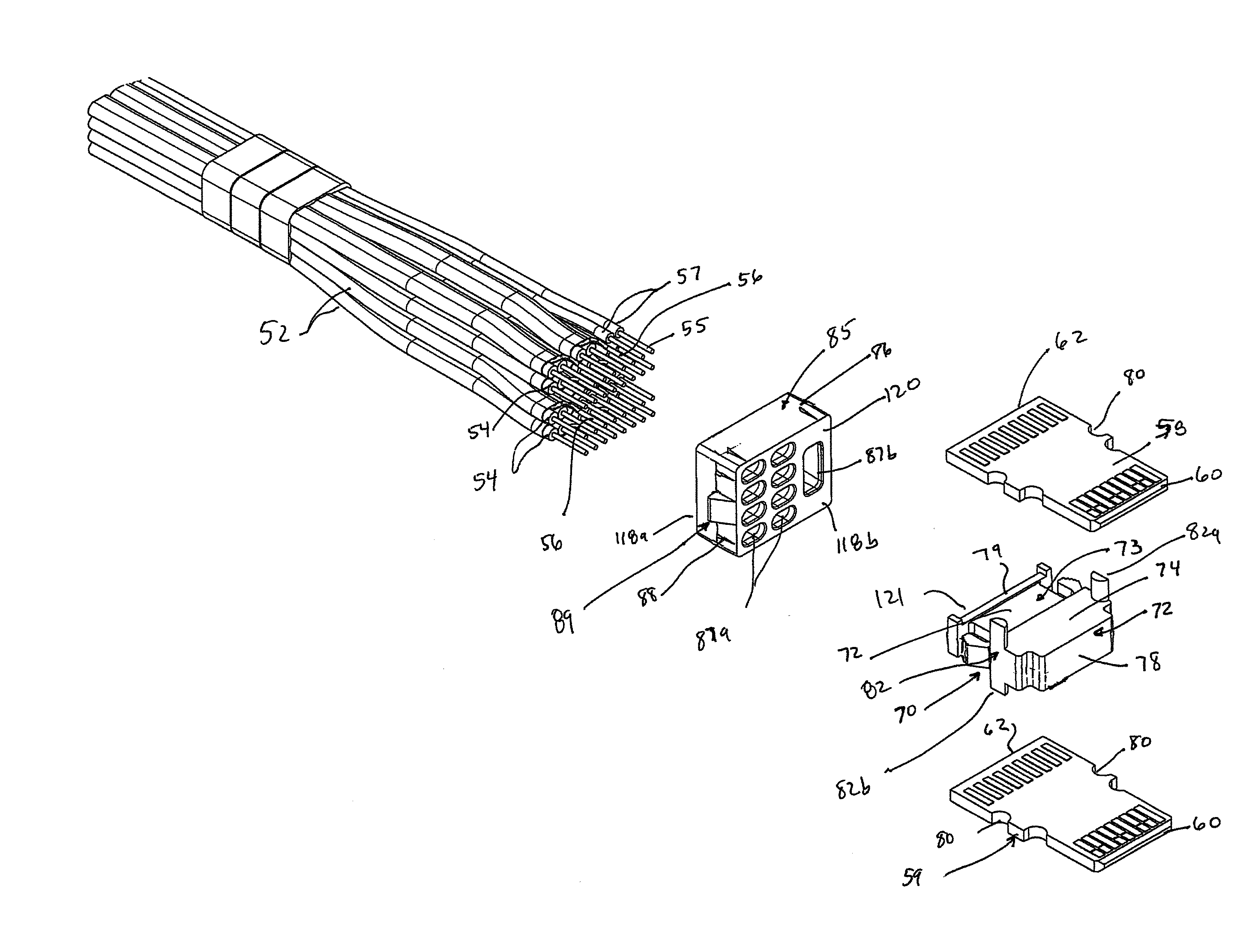
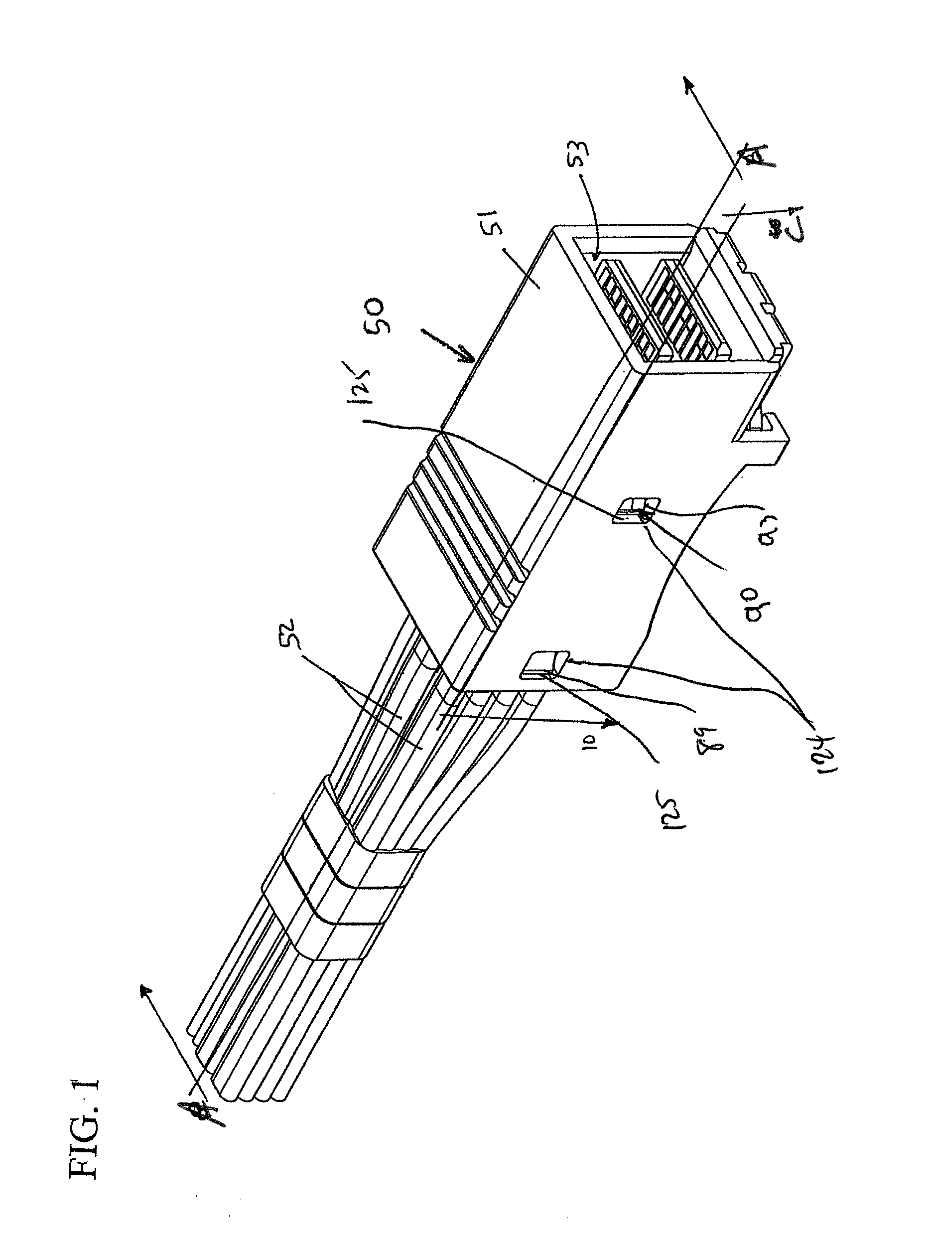
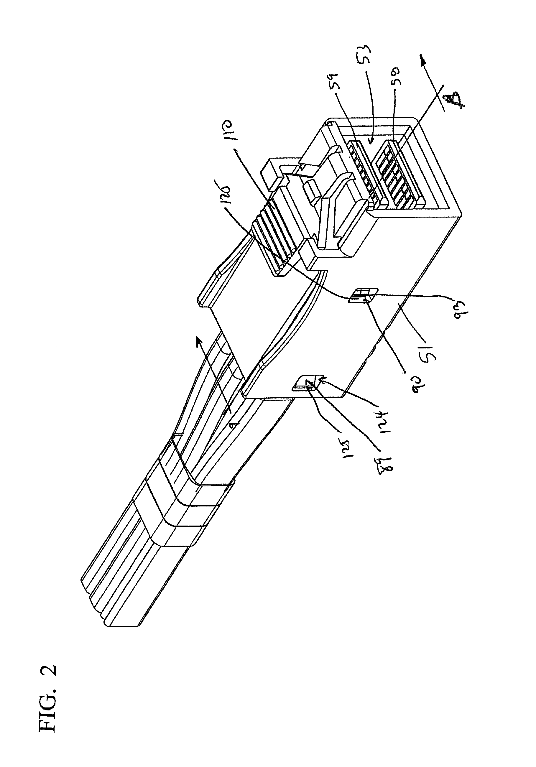
[0038]FIG. 1 illustrates a plug connector 50 constructed in accordance with the following detailed disclosure. The connector 50 is a plug style connector that is used to electrically connect a plurality of multi-wire cables 52, each containing multiple wires 54 with associated conductors 55. Some of the cables contain pairs of wires which are used to transmit differential signals across the wire pairs. As such, the cables 52 are referred to in the art as “twinax” cables that are used to transmit differential signals, and each such wire pair includes an associated ground, or drain wire 56. The wires 54 of the cable 52 are terminated to printed circuit boards 58, 59 that are elongated in nature and have a general rectangular configuration. Such printed circuit boards are known in the art as “paddle cards” and each such board has opposing leading and trailing edges, or ends 60, 62. The connector 50 includes an elongated hollow connector housing 51 with a hollow passage 53 extending the...


PUM


Abstract

A plug style connector has an outer connector housing with an internal passage which accommodates a cable assembly. A plurality of multi-wire cables extend through a wire organizer that arranges the cables in a preselected arrangement. Exposed free ends of the conductors of the wires are terminated to multiple circuit boards which are separated in a preselected spacing by a spacer member. The spacer member and wire organizer have flat opposing surfaces that define boundaries of a body portion formed by the application of a hot melt to the cables, the hot melt adheres to the wire organizer and the spacer to hold the cable wires and their associated circuit boards in place for correct insertion into the connector housing.

Description

BACKGROUND OF THE PRESENT DISCLOSURE[0001]The Present Disclosure relates generally to the construction of plug connectors and, more particularly, to high-speed plug connectors having improved impedance characteristics.[0002]Many different styles of cable connectors are known. One such connector is described in U.S. Pat. No. 7,175,444, the contents of which are incorporated by reference herein in its entirety. In the connector disclosed in the '444 patent, cable wires are connected to contact pads on a printed circuit board used as a mating blade of the connector. The wires are terminated to the contact pads in a termination nest area and then overmolded with plastic. The plastic has a higher dielectric constant than air and, as such, affects the impedance of the connector, typically by lowering it in that area. The resultant dip in impedance may be detrimental to the operation of the connector based upon its magnitude. At low operational speeds and data transmission rates, such as 1...

Claims


Application Information

Patent Timeline
Patent Type & Authority Applications(United States)
IPC IPC(8): H01R31/00
CPCH01R9/034H01R31/00H01R13/504H01R12/62H01R13/65914
Inventor SYTSMA, PETER H.DOYE, DENNIS L.REED, BRUCE A.CRANE, JOHN REGINALDLLOYD, BRIAN KEITHLANG, KAITH
Owner MOLEX INC
Why Eureka
Try Eureka