Component for conveying gases

a technology for conveying gases and components, applied in the field of components for medical circuits, can solve the problems of condensation or rainout,/or various sensors, and affecting the performance of connected equipment and ancillary devices

Active Publication Date: 2013-09-12
FISHER & PAYKEL HEALTHCARE LTD
View PDF17 Cites 34 Cited by
  • Summary
  • Abstract
  • Description
  • Claims
  • Application Information

AI Technical Summary

Benefits of technology

[0015]It is an object of the present invention to provide a component and / or method of manufacturing a component that will at least go some way towards improving on the above or which will at least provide the public and the medical profession with a useful choice.

Problems solved by technology

If the expired gas is allowed to cool as it passes along an expiratory breathing tube, condensation or rain-out may also occur.
Condensate forming in a breathing tube (either inspiratory or expiratory) can be breathed or inhaled by a patient and may lead to coughing fits or other discomfort.
Condensation within a breathing tube may also interfere with the performance of connected equipment and ancillary devices and / or various sensors.
This temperature is typically maintained by a heater wire within the breathing tube, although the rain-out performance of these breathing tubes may not be complete due to a number of factors.
Further, previous methods of heating the gases flow to reduce rain-out, typically result in heated tubing that has been expensive and / or difficult to manufacture.
Particularly, in ‘single use’ applications such as typically found in hospital applications, the manufacturing cost of breathing tubes is critically important.
Any vapour condensing on the filter and run-off along the limbs (inlet or exhaust) from moisture is highly undesirable.
For example water which has condensed on the walls, can saturate the filter and cause it to become blocked.
This potentially causes an increase in back pressure and hinders the ability of the system to clear smoke.
Further, liquid water in the limbs can run into other connected equipment which is undesirable.

Method used


Image

  • Component for conveying gases
  • Component for conveying gases
  • Component for conveying gases

Examples


Embodiment Construction

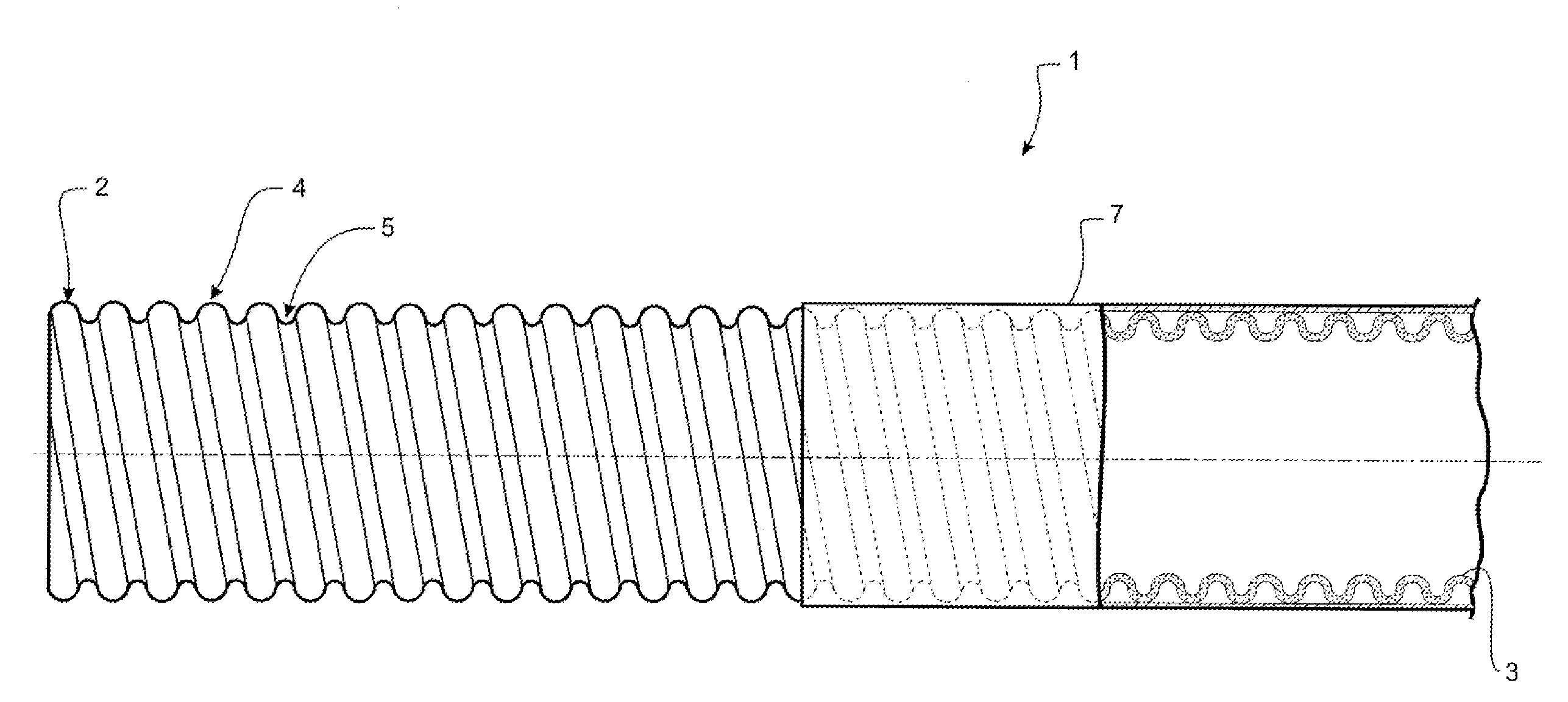
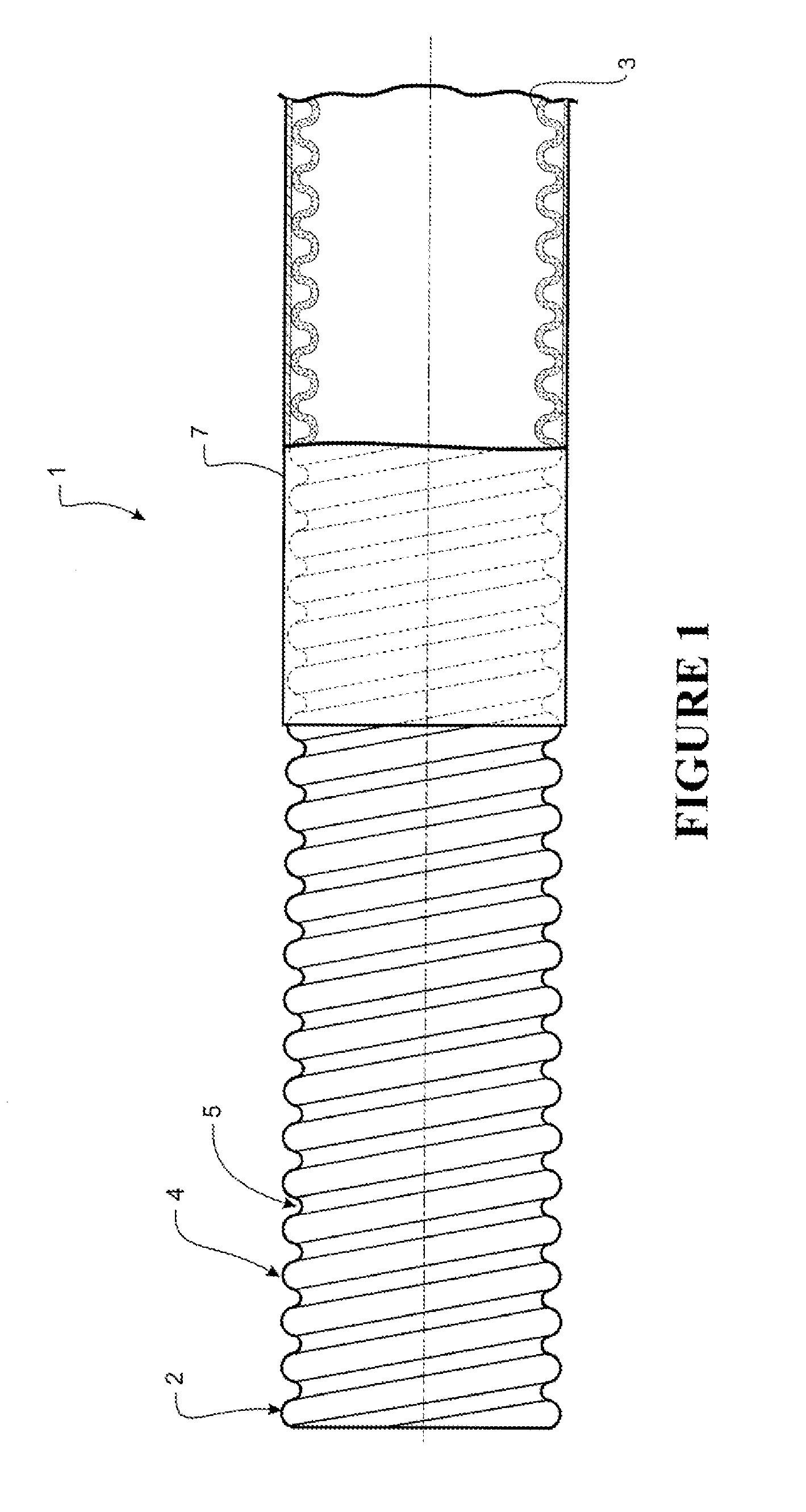
[0130]In the field of medical circuits, and in particular breathing circuits (including anaesthetic circuits), condensation or rain-out can be a particular problem where high humidity breathing gases come into contact with the walls of a component at a relatively lower temperature. Enhancing the thermal resistance (or thermal insulation capabilities) of the walls provides benefits in this respect. However, it remains beneficial for a user or care-giver to be able to optically identify or visually discern the presence of liquid or build-up of condensate within the component. The present invention is directed toward enabling a component providing a patient and care-giver with both of these beneficial requirements.

[0131]With reference to FIG. 3 a humidified ventilation system is shown in which a patient 100 is receiving humidified and pressurised gases through a patient interface 102 connected to a humidified gases transportation pathway or inspiratory breathing tube 103. It should be ...


PUM

PropertyMeasurementUnit
thicknessaaaaaaaaaa
thicknessaaaaaaaaaa
wt. %aaaaaaaaaa

Abstract

This invention provides for a component forming a part of a breathing tube, or forming the breathing tube, for example as a part of a breathing circuit for respiratory therapy. The component comprising a tubular body having a foamed wall. The foamed wall can be formed from extrusion of a single extrudate. The foamed wall is of a sufficient minimum optical transparency such that, in use, there is enabled the visual detection of a liquid (or condensate that may have formed) within the tubular body.

Description

INCORPORATION BY REFERENCE TO ANY PRIORITY APPLICATIONS[0001]Any and all applications for which a foreign or domestic priority claim is identified in the Application Data Sheet as filed with the present application, are hereby incorporated by reference under 37 CFR 1.57.BACKGROUND OF THE INVENTION[0002]1. Field of the Invention[0003]The present invention relates to components for medical circuits for conveying gases to and / or from a patient. In one particular aspect, the invention relates to conduits and in particular to breathing tubes for use in an inspiratory and / or expiratory limb of a breathing circuit. In another particular aspect the invention relates to a tube for a surgical insufflation system.[0004]2. Description of the Related Art[0005]In assisted breathing, particularly in medical applications, gases having high levels of relative humidity are supplied and returned through flexible breathing tubes of a relatively restricted size typically between a range of approximately...

Claims


Application Information

Patent Timeline
Patent Type & Authority Applications(United States)
IPC IPC(8): A61M16/08B29C48/09B29C48/13B29C48/30B29C48/32
CPCA61M13/003A61M16/1095A61M16/16A61M2205/3633A61M2205/583A61M2207/00A61M2207/10B29C47/0023B29C47/0033B29C47/126B29C47/20B29K2105/04B29L2023/007F16L11/111F16L53/008A61M16/0808A61M16/0875A61M2205/7545A61M13/006F16L53/38B29C48/09B29C48/13B29C48/303B29C48/32B29C48/30A61M16/00A61M2205/0233
Inventor GRAHAM, PETER KENNETHGARCIA, ENRICO ALVAREZCHU, SHU-YI
Owner FISHER & PAYKEL HEALTHCARE LTD
Why Eureka
Try Eureka