Transport system and transport method

a technology which is applied in the field of transport system and transport method for transporting sample holder receptacles, can solve the problem of high maintenance performance and the need for a simple transport system

Inactive Publication Date: 2013-09-12
AOI SEIKI
View PDF0 Cites 12 Cited by
  • Summary
  • Abstract
  • Description
  • Claims
  • Application Information

AI Technical Summary

Benefits of technology

[0007]According to an embodiment, a transport system configured to transport a receptacle which accommodates an upright sample holder containing a sample, the transport system comprising a screw comprising a rotatable shaft disposed along a predetermined transport path and a helical ridge protruding outward from an outer peripheral surface of the shaft, and a drive unit configured to rotate the screw.
[0043]The same effect as in the first embodiment can also be obtained in the present embodiment. Specifically, the screw 20 has guide and feed functions, so that the parts count can be reduced and the system configuration can be simplified. Since the screw 20 is made of a molded plastic piece, moreover, its manufacturing costs can be suppressed. Since the transport does not require the use of a belt, furthermore, belt replacement is unnecessary, so that the maintenance performance is improved, and the necessity of a user's check can be reduced. Further, a plurality of receptacles 12 that are positioned at regular intervals can be accurately transported at a constant speed by the screw 20, so that this transport system is particularly excellent as a transport mechanism of a sample processing device. According to the present embodiment, moreover, the single simple screw 20 should only be rotated, so that the control processing and system configuration can be simplified.

Problems solved by technology

According to the belt-drive transport system described above, the system configuration and maintenance work are so complicated that there is a demand for a simple transport system with high maintenance performance.

Method used


Image

  • Transport system and transport method
  • Transport system and transport method
  • Transport system and transport method

Examples


first embodiment

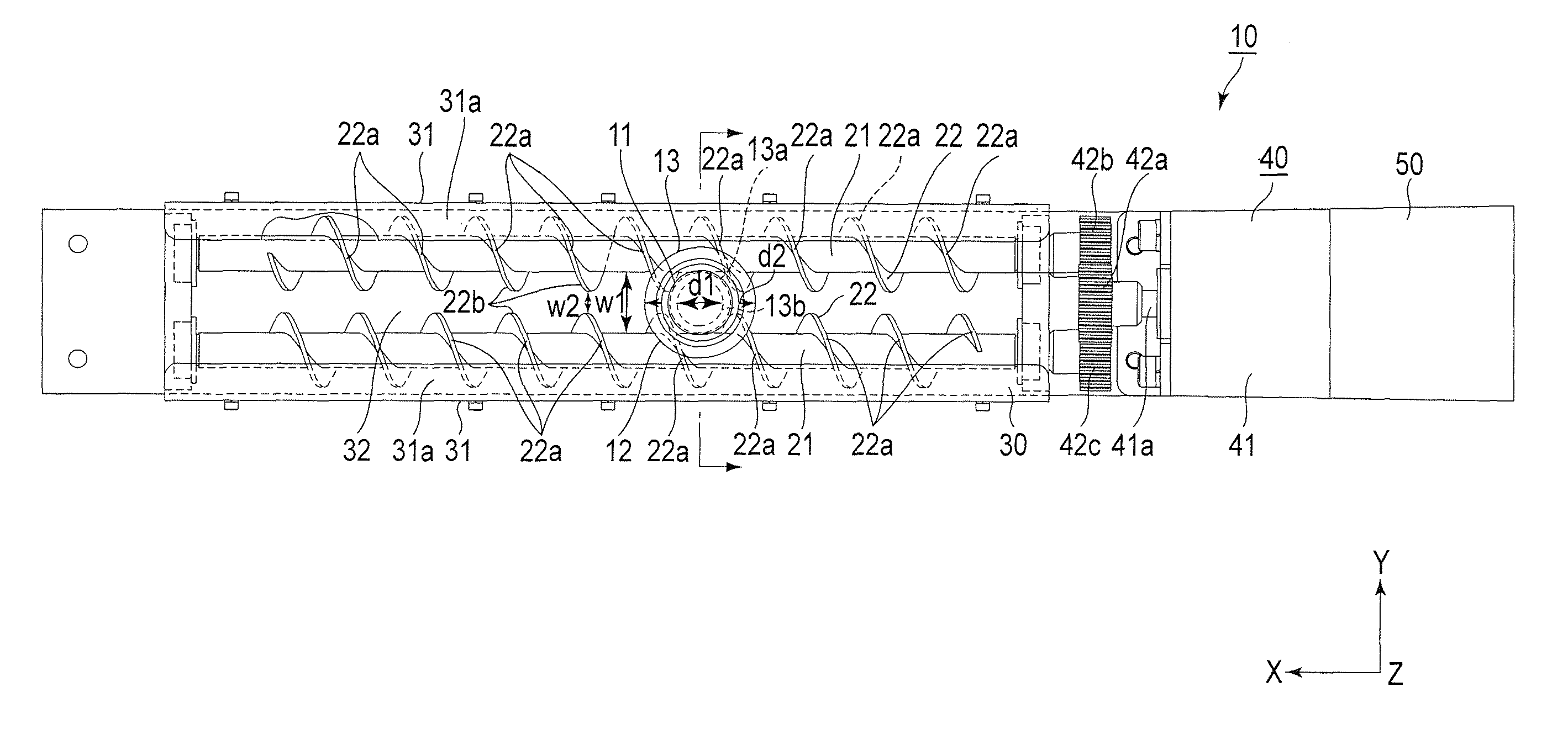
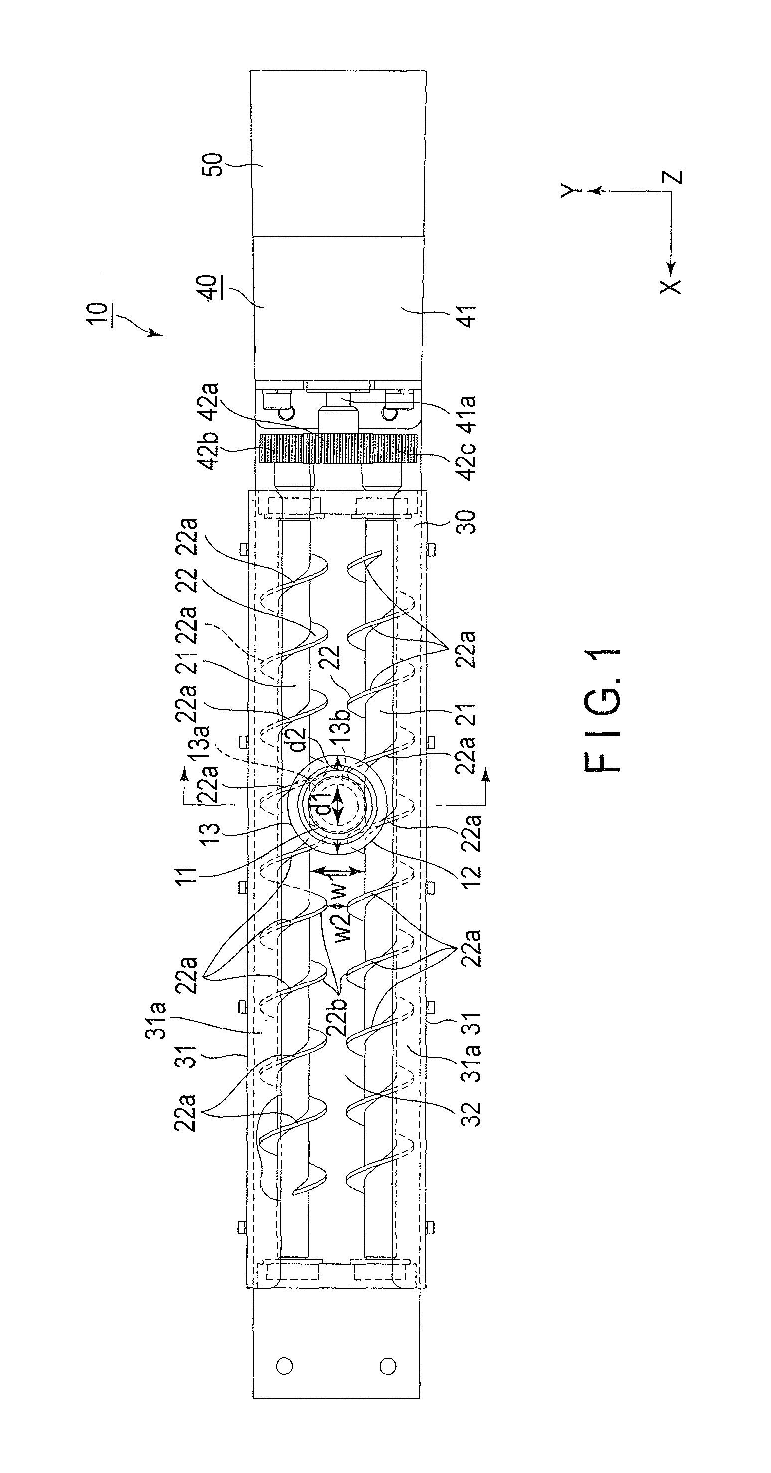
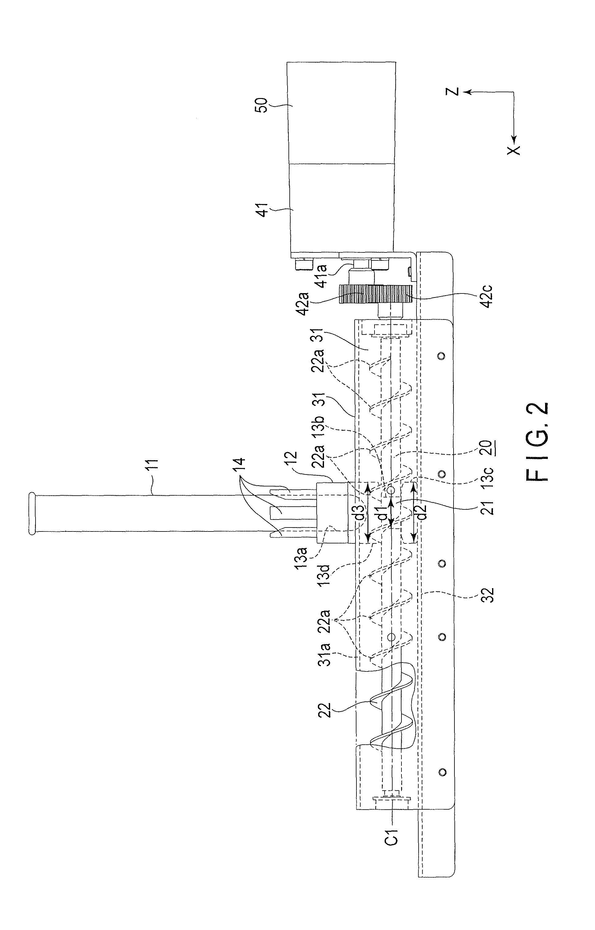
[0016]The following is a description of a transport system 10 according to a first embodiment of the invention. FIGS. 1, 2 and 3 are a plan view, side view, and sectional view, respectively, of the transport system 10 of the present embodiment. In these drawings, some structural elements are enlarged or reduced in scale or omitted for ease of illustration, and arrows X, Y and Z indicate three orthogonal directions, individually.

[0017]The transport system 10 has the function of transporting a receptacle 12 for accommodating a test tube as a sample holder 11, which contains a sample such as blood, from one end side toward the other end in a transport direction along the arrow X.

[0018]The transport system 10 comprises a screw 20, frame 30, drive unit 40, and control unit 50. The screw 20 is located extending along a predetermined transport path. The frame 30 comprises a pair of guide rails 31 disposed spaced on the opposite sides of the screw 20. The drive unit 40 serves to rotate the ...

second embodiment

[0037]The following is a description of a transport system 100 according to a second embodiment of the invention. FIGS. 4, 5 and 6 and are a plan view, side view, and sectional view, respectively, of the transport system 100 of the present embodiment. In these drawings, some structural elements are enlarged or reduced in scale or omitted for ease of illustration, and arrows X, Y and Z indicate three orthogonal directions, individually.

[0038]The transport system 100 according to the present embodiment comprises a single screw 20, frame 30, drive unit 40, and control unit 50. The screw 20 is located extending along a predetermined transport path. The frame 30 comprises a pair of guide rails 31 disposed spaced and supporting the opposite sides of the screw 20. The drive unit 40 serves to rotate the screw 20. The control unit 50 controls the operation of the drive unit 40.

[0039]The transport system 100 of this embodiment differs from the transport system 10 of the first embodiment in th...


PUM


Abstract

According to an embodiment, a transport system configured to transport a receptacle which accommodates an upright sample holder containing a sample, the transport system including a screw includes a rotatable shaft disposed along a predetermined transport path and a helical ridge protruding outward from an outer peripheral surface of the shaft, and a drive unit configured to rotate the screw.

Description

CROSS-REFERENCE TO RELATED APPLICATIONS[0001]This application is based upon and claims the benefit of priority from Japanese Patent Application No. 2012-052121, filed Mar. 8, 2012, the entire contents of which are incorporated herein by reference.BACKGROUND OF THE INVENTION[0002]1. Field of the Invention[0003]Embodiments of the present invention relate to a transport system and a transport method for transporting sample holder receptacles.[0004]2. Description of the Related Art[0005]A belt-drive transport system (e.g., Jpn. Pat. Appln. KOKAI Publication No. 2005-263478) is a known example of a system for transporting sample holders configured to contain samples such as blood. This system comprises a belt, rotating rollers, a feed mechanism such as a motor, and a pair of guide rails. The belt is stretched over a base extending in a transport direction. The rollers are arranged beneath the belt. The feed mechanism rotates the rollers to feed the belt. The guide rails are disposed spac...

Claims


Application Information

Patent Timeline
Patent Type & Authority Applications(United States)
IPC IPC(8): B65G33/06
CPCB65G33/06G01N2035/0487G01N2035/0406G01N35/04F16H25/20G01N33/49G01N35/10
Inventor ITOH, TERUAKI
Owner AOI SEIKI
Why Eureka
Try Eureka