Fuel injection valve
a technology of fuel injection valve and valve body, which is applied in the direction of fuel injection apparatus, charge feed system, spraying apparatus, etc., to achieve the effect of increasing the degree of freedom
- Summary
- Abstract
- Description
- Claims
- Application Information
AI Technical Summary
Benefits of technology
Problems solved by technology
Method used
Image

Examples
first embodiment
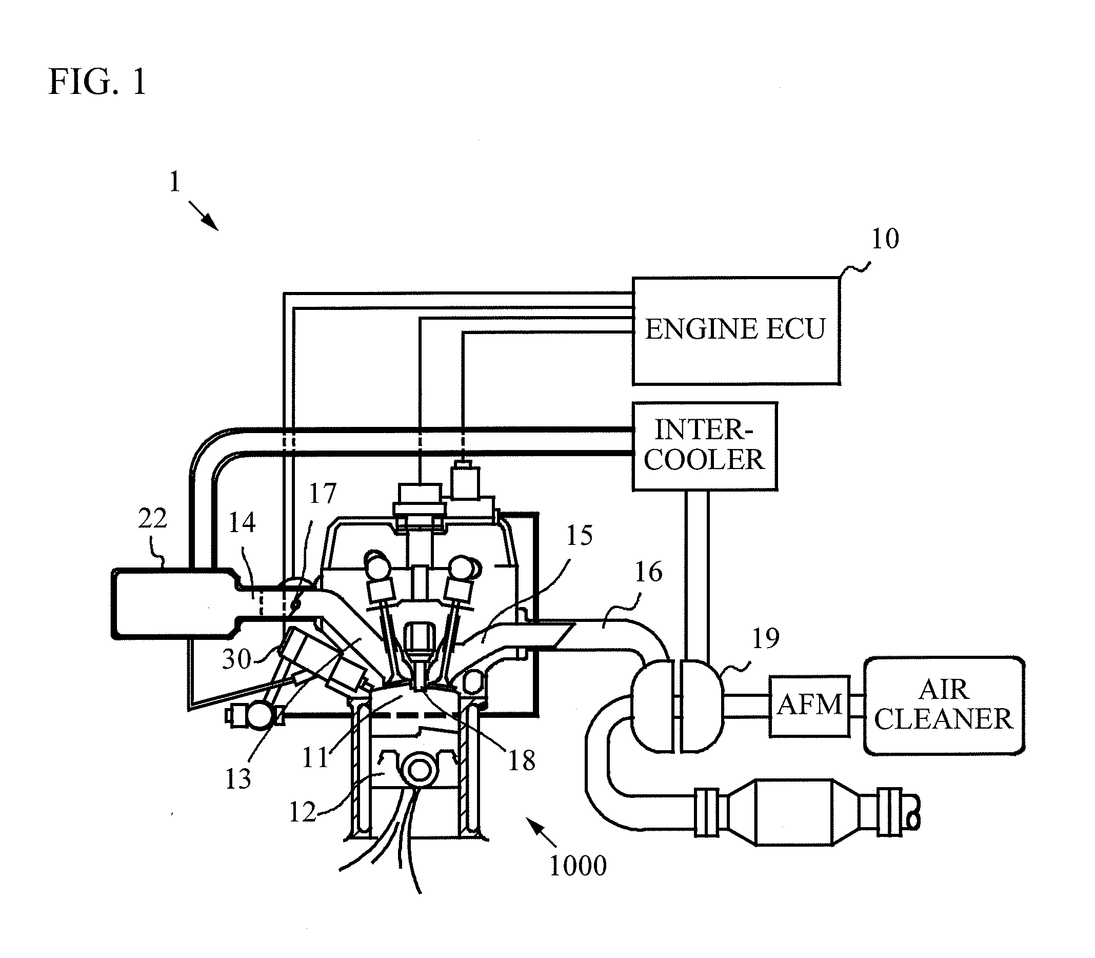
[0036]A description will now be given of a first embodiment of the present invention with reference to drawings. FIG. 1 is a diagram illustrating a configuration of an engine system 1 to which a fuel injection valve 30 of the present invention is installed. FIG. 1 illustrates only a part of the components of an engine 1000.
[0037]The engine system 1 illustrated in FIG. 1 includes the engine 1000 that is a power source, and an engine ECU (Electronic Control Unit) 10 that overall controls operation of the engine 1000. The engine system 1 includes fuel injection valves 30 that inject fuel into combustion chambers 11 of the engine 1000. The engine ECU 10 has a function as a controller. The engine ECU 10 is a computer including a CPU (Central Processing Unit) that performs arithmetic processing, a ROM (Read Only Memory) that stores programs and the like, and a RAM (Random Access Memory) or NVRAM (Non Volatile RAM) that stores data and the like.
[0038]The engine 1000 is an engine mounted on...
second embodiment
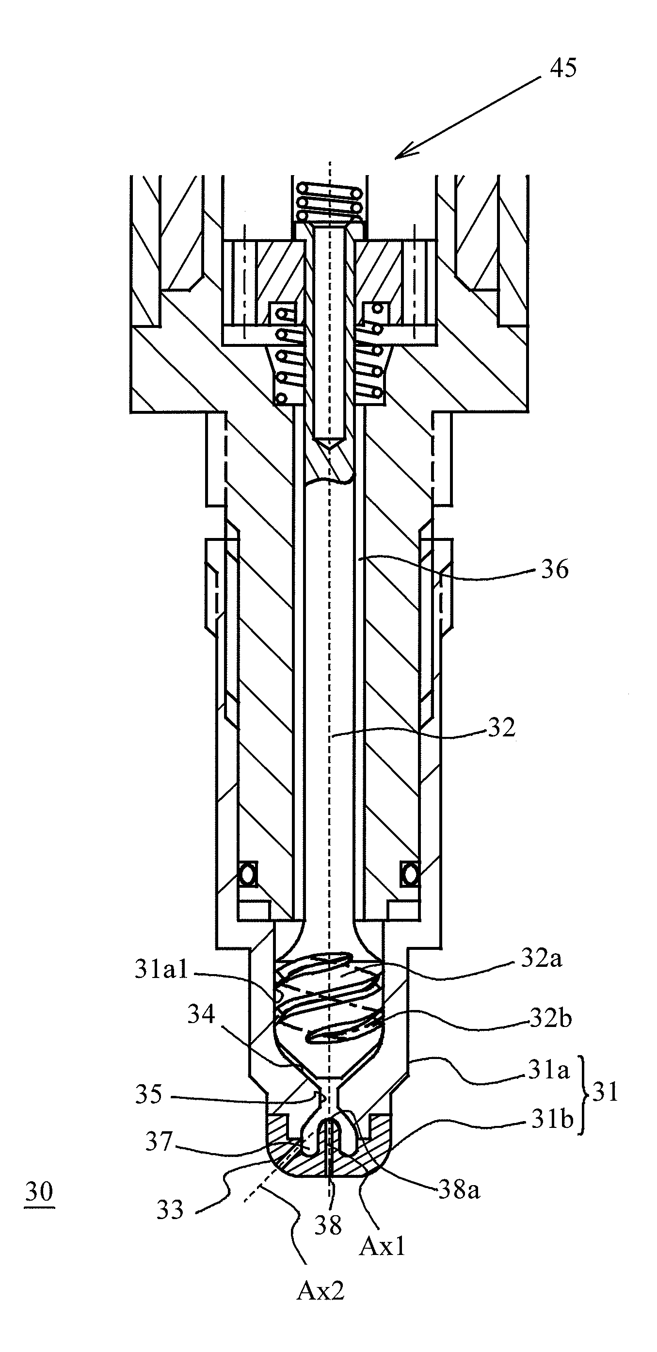
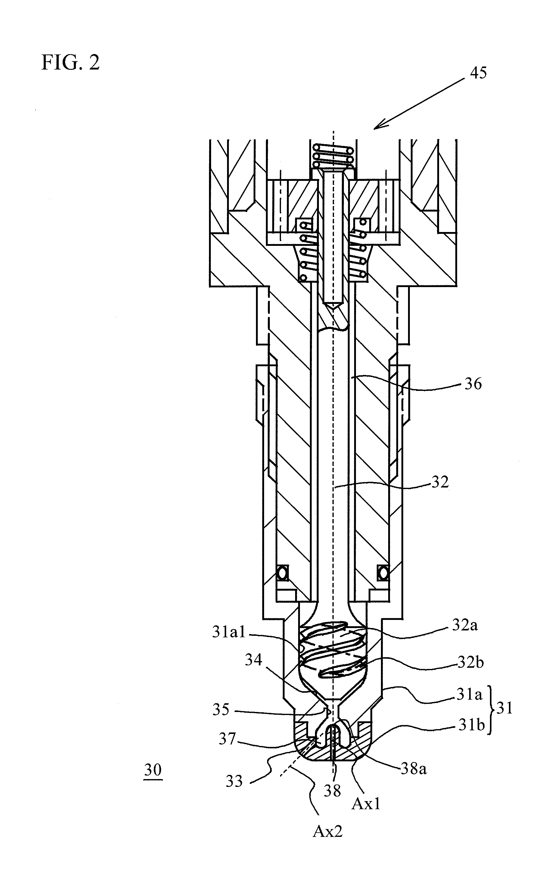
[0062]A description will now be given of a second embodiment with reference to FIG. 5. FIG. 5 is an explanatory diagram illustrating a tip portion of the fuel injection valve 30 of the second embodiment. The second embodiment differs from the first embodiment in the following respects. That is to say, the needle 32 of the second embodiment includes an air reserve chamber 39 in a position facing the gas introduction hole 38. Other configuration are the same between the first embodiment and the second embodiment, and thus the same reference numerals are affixed to the common components in the drawing, and a detail description thereof is omitted.
[0063]The air reserve chamber 39 is a hollow portion located in the needle 32. The air reserve chamber 39 facing the gas introduction hole 38 allows to obtain the following effect.
[0064]A negative pressure generated by the swirling flow in the swirl velocity increasing portion 35 causes burnt gas inhaled from the outside (combustion chamber sid...
third embodiment
[0067]A description will now be give of a third embodiment with reference to FIG. 6. FIG. 6 is an explanatory diagram illustrating a tip portion of a fuel injection valve 50 of the third embodiment, FIG. 6A is a diagram illustrating an opened state of the valve, and FIG. 6B is a bottom view. FIG. 6A is a cross sectional view taken along line A-A in FIG. 6B. A fundamental configuration of the fuel injection valve 50 is in common with that of the fuel injection valve 30 of the first embodiment. That is to say, the fuel injection valve 50 includes a nozzle body 51 including a main body portion 51a and a nozzle plate 51b, a needle 52, and the seat portion 54. In addition, a fuel introduction path 56 is formed in the fuel injection valve 50. Further, the fuel injection valve 50 includes a swirling flow generating portion 52a and a spiral groove 52b as the fuel injection valve 30 does. In addition, a swirl velocity increasing portion 55 and an air bubble reserving portion 57 are also incl...
PUM
 Abstract
Description
Claims
Application Information
 - R&D
- Intellectual Property
- Life Sciences
- Materials
- Tech Scout
- Unparalleled Data Quality
- Higher Quality Content
- 60% Fewer Hallucinations
Browse by: Latest US Patents, China's latest patents, Technical Efficacy Thesaurus, Application Domain, Technology Topic, Popular Technical Reports.
© 2025 PatSnap. All rights reserved.Legal|Privacy policy|Modern Slavery Act Transparency Statement|Sitemap|About US| Contact US: help@patsnap.com