Eureka AIR delivers breakthrough ideas for toughest innovation challenges, trusted by R&D personnel around the world.

Replaceable electrical ballast tube

Inactive Publication Date: 2013-09-12
JUSTENERGY TECH CORP
View PDF1 Cites 2 Cited by
  • Summary
  • Abstract
  • Description
  • Claims
  • Application Information

AI Technical Summary

Benefits of technology

The present invention provides a replaceable electrical ballast tube that can be directly installed on traditional fluorescent lamp holders and used with the existing electrical ballast. This avoids the need to purchase a new compatible lamp, uninstall the electrical ballast or rearrange the wiring.

Problems solved by technology

However, when a LED tube is installed in the traditional fluorescent lamp, the high starting voltage generated by the resonance may lead to collapsing and burning of the LED.
Therefore, the LED tube is not compatible to be applied directly to the traditional fluorescent lamp with the traditional electrical ballast.
The starting method and frequent switching on and off also causes the two ends of the fluorescent tube to be blackened, leading to shorter life and lower luminous efficiency of the fluorescent lamp.
This may create inconvenience of consumers and a barrier of promoting energy saving and green energy.

Method used


Image

  • Replaceable electrical ballast tube
  • Replaceable electrical ballast tube
  • Replaceable electrical ballast tube

Examples


Embodiment Construction

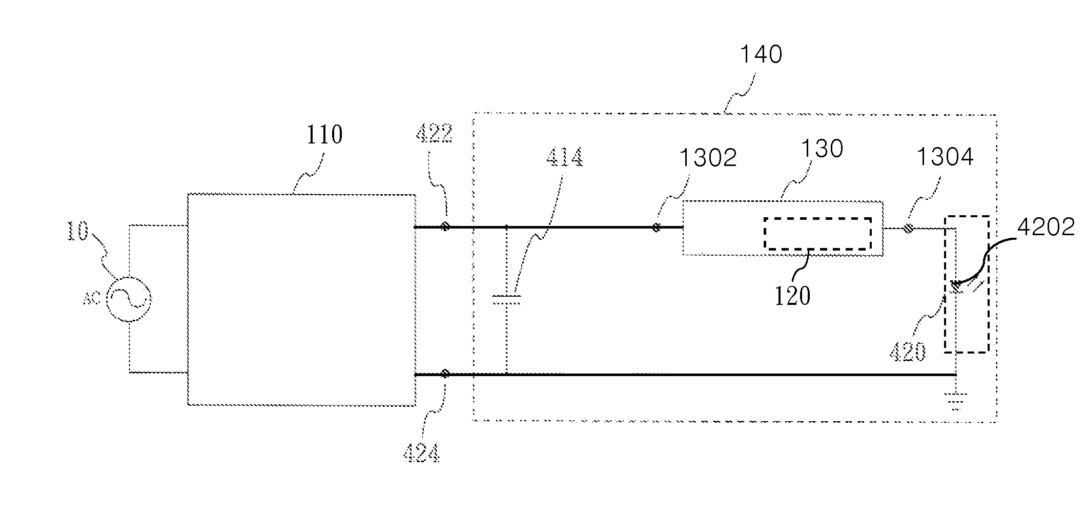
[0012]The present invention provides a replaceable electronic ballast tube, which can be applied to lamp holders equipped with electronic ballast in related arts. In order to understand the goals, characteristics, and functions of this invention, the following embodiments and examples are revealed with the reference to figures to explain the concept of the invention specifically in detail.

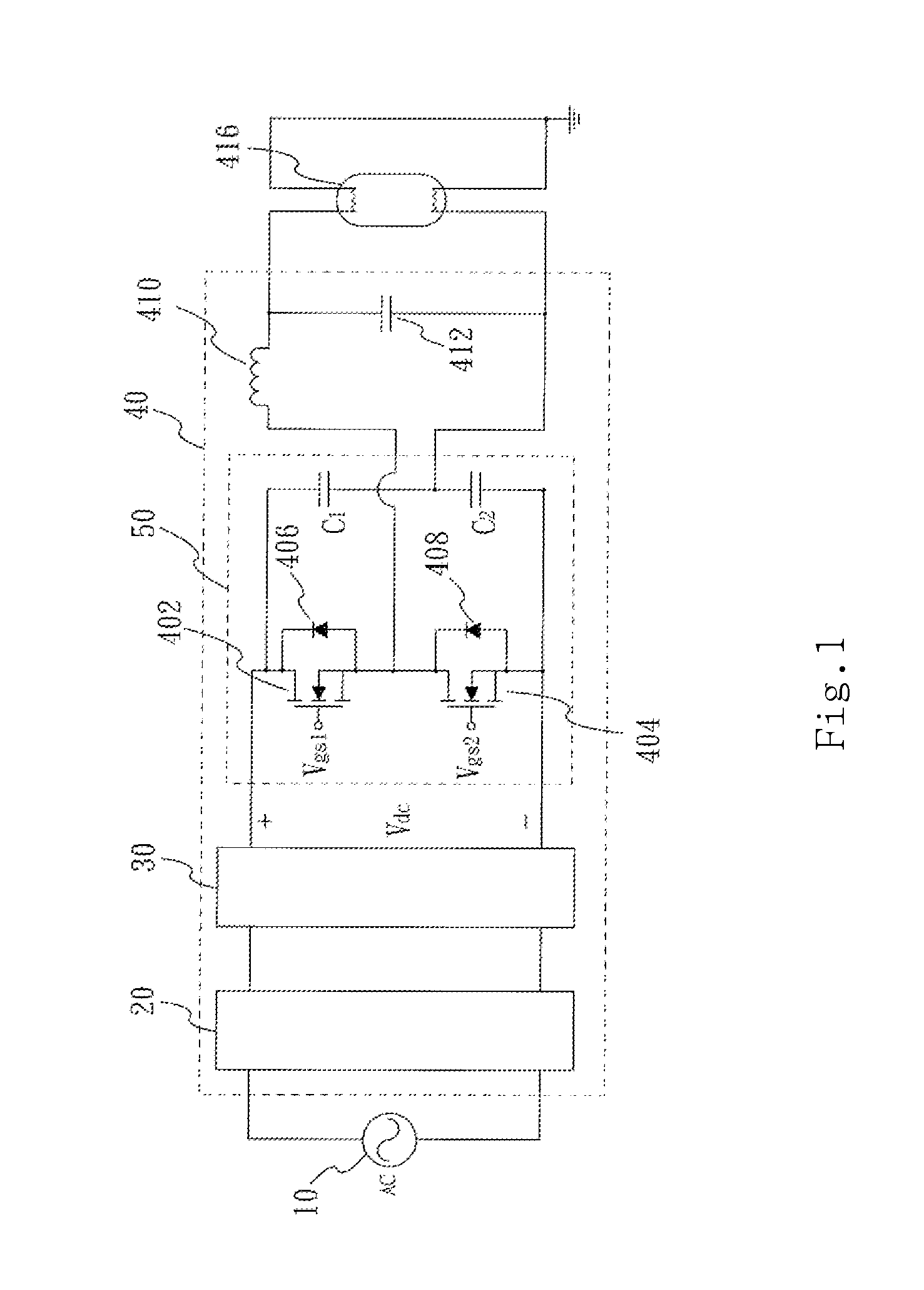
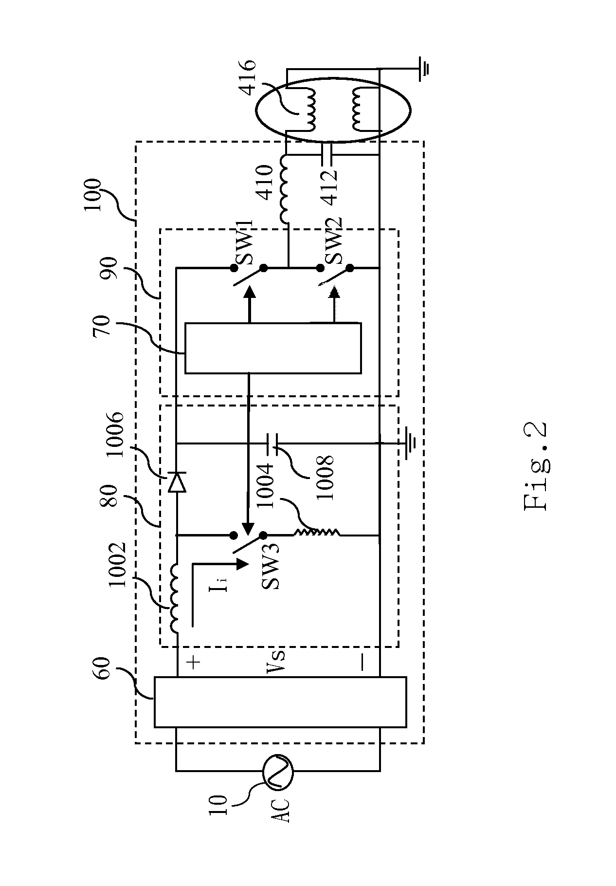
[0013]Firstly, referring to FIG. 1, which is a schematic diagram of the circuit structure of resonant electronic ballast connected in series in related arts, this figure shows that the resonant electronic ballast in series receives AC voltage generated by AC power (10). The AC voltage is further transferred to ballast rectifying unit (20). The AC voltage generates a DC voltage after being rectified by the ballast rectifying unit (20) and the DC voltage is provided to a power factor corrector (30). The power factor corrector (30), which is a DC to DC converting circuit, can control the timing of swi...


PUM


Abstract

A replaceable electrical ballast tube is disclosed to be applied to a lamp holder with an electrical ballast. The tube includes a capacitor, a rectifier, a current limiting unit and a light-emitting module. The capacitor is connected in parallel with the electrical ballast to filter an AC voltage generated by the electrical ballast with high frequency and high voltage. The rectifier is connected in parallel with the capacitor to rectify the AC voltage to a DC voltage. The current limiting unit converts the DC voltage to a corresponding DC current. The DC current is provided to the light-emitting module to generate light. Accordingly, the tube can be directly used in the lamp holder of a traditional fluorescent lamp without changing the wiring of the lamp holder.

Description

FIELD OF THE INVENTION[0001]The present invention relates to a replaceable electrical ballast tube, especially a light-emitting diode (LED) tube that can be applied to traditional lamp holders equipped with electrical ballasts.BACKGROUND OF THE INVENTION[0002]After decades of research and experimental development, the manufacturing technology of LED has been profoundly enhanced. LED has been widely applied to replace the traditional fluorescent tube as a new light source in various fields because of its advantages of small size, pollution-free, effective energy-saving, long life, and high luminous efficiency. Currently, a LED module disposed in a transparent tube is utilized mostly as the structure of the LED devices available in the market, and the plug connector design of the fluorescent tubes in the related arts is used as the plug connector of the LED devices.[0003]Currently, the traditional fluorescent tubes installed in modern buildings utilize traditional electrical ballasts ...

Claims


Application Information

Patent Timeline
IPC IPC(8): H05B37/00
CPCY02B20/386H05B33/0803H05B45/3578Y02B20/30
Inventor YU, CHUNG-HUNGCHEN, HSUAN-HUIFU, HAO-JANLIU, CHIN-TSAI
Owner JUSTENERGY TECH CORP
Why Eureka
Eureka Blog
Learn More