Solid state relay circuit

a solid-state relay and circuit technology, applied in electronic switching, pulse technique, semiconductor devices, etc., can solve the problems of low power supply of opto-isolators, potential mechanical shock or vibration, and the use of transformers in high-shock environments, so as to achieve quick enable and disable

Active Publication Date: 2013-09-12
MCQ INC
View PDF8 Cites 30 Cited by
  • Summary
  • Abstract
  • Description
  • Claims
  • Application Information

AI Technical Summary

Problems solved by technology

However, transformers should not be used in high shock environments, where there is a potential for mechanical shock or vibration.
Photodiode opto-isolators may be used to control gates in a power switching stage; however, photodiode opto-isolators provide very little power and take a long time to charge the gates to switch the power supply.
In addition to the ½ cycle maximum turn-off time, TRIAC and SCR based solid state relays can have issues when powering a low power factor load.
This can cause the solid state relays to latch up into the on-state.

Method used


Image

  • Solid state relay circuit
  • Solid state relay circuit
  • Solid state relay circuit

Examples


example embodiments

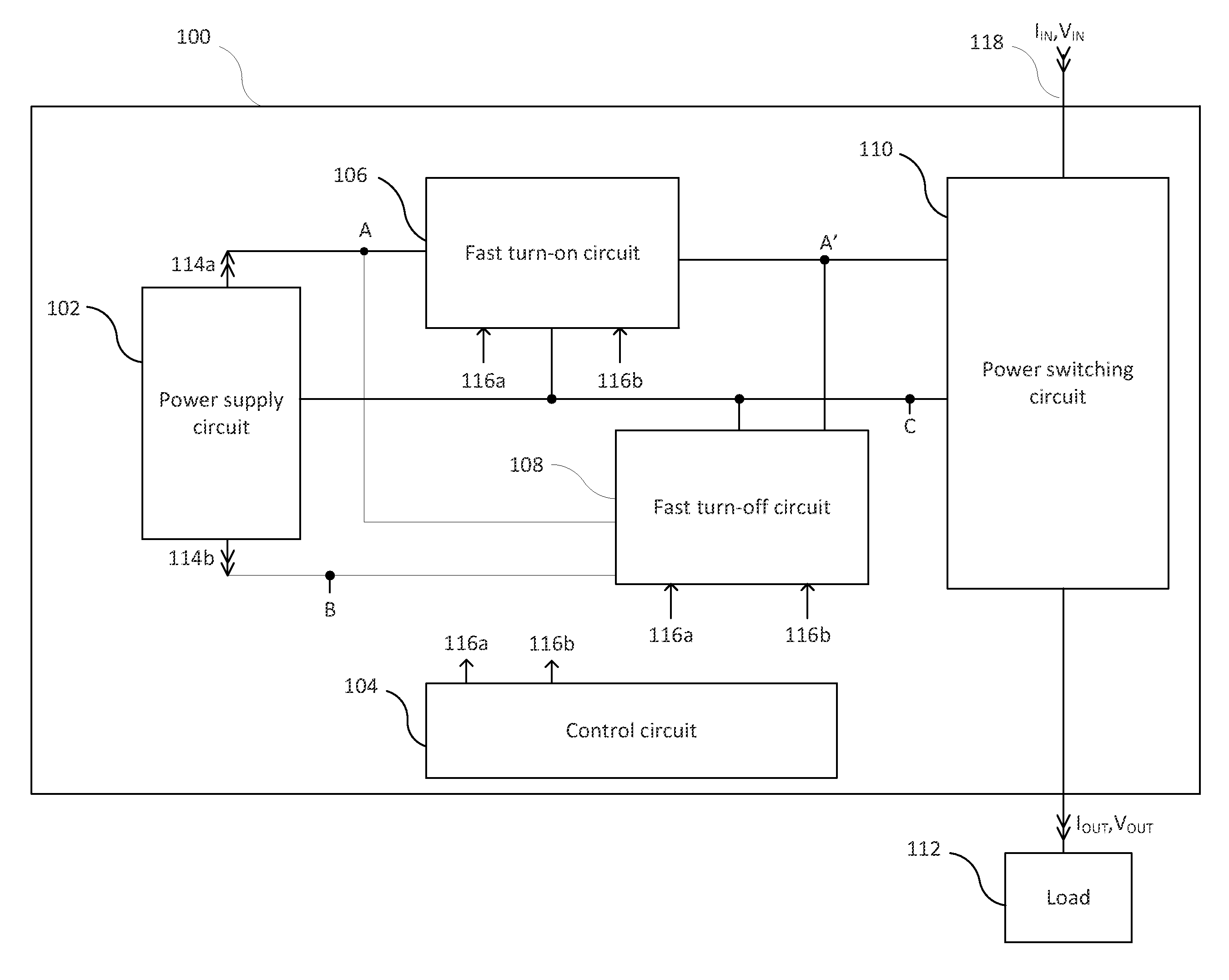
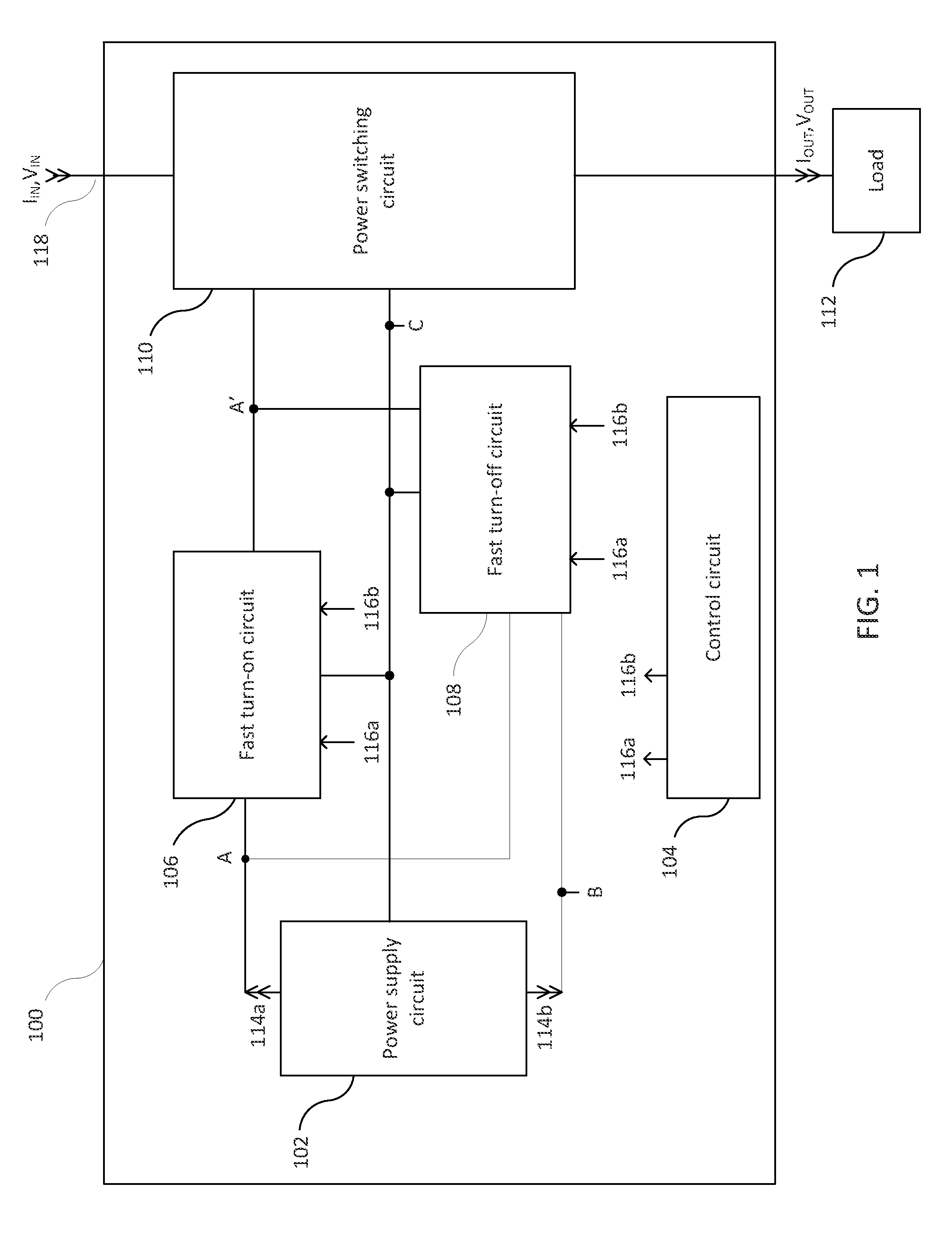
[0029]The example embodiments described herein are provided for illustrative purposes, and are not limiting. In embodiments, a solid state relay for providing fast switching is provided. Different circuit configurations may be used, including using voltage controlled devices such as MOSFETs or other types of field effect transistors (FETs), IGBTs (insulated gate bipolar transistors), and / or optical isolation. The example embodiments described herein may be adapted to any type of semiconductor technology. Further structural and operational embodiments, including modifications / alterations, will become apparent to persons skilled in the relevant art(s) from the teachings herein.

[0030]A solid state relay as disclosed herein provides very fast power switching speeds using solid state electronics while being robust enough to handle voltage transients and inrush currents, such as may occur in otherwise normal operations, even in the event of severe mechanical shock or vibrations. In an emb...


PUM


Abstract

A solid state relay and method for enabling and disabling power to a load are disclosed. A fast turn-on circuit and fast turn-off circuit receive control signals in an isolated manner. The control signals allow only one of the fast turn-on circuit and fast turn-off circuit to be enabled at a time. A power switching circuit that enables power to be supplied to a load when the fast turn-on circuit is enabled and the fast turn-off circuit is disabled state, and disables the power from being supplied to the load when the fast turn-on circuit is disabled and the fast turn-off circuit is enabled. A power supply circuit provides isolated power used by the fast turn-on and fast turn-off circuits to drive or discharge a gate in the power switching circuit.

Description

STATEMENT REGARDING FEDERALLY SPONSORED RESEARCH OR DEVELOPMENT[0001]This invention was made with government support under Contract No. N00167-11-P-0134 awarded by the United States Naval Sea Systems Command Small Business Innovation Research (SBIR) Program. The government may have certain rights in the invention.BACKGROUND OF THE INVENTION[0002]1. Field of the Invention[0003]The present invention relates to the switching of power to a load, and more particularly, to solid state relays and methods for switching power to a load very quickly.[0004]2. Background Art[0005]Relays are electrically controlled switching devices. Electromechanical relays provide switching with a mechanical device typically controlled by an electromagnet. Solid state relays use semiconductors to provide switching. Solid state relays are frequently used to control a power supply to a load. Typically, a low voltage control signal is applied to a semiconductor switch to enable or disable a higher voltage power s...

Claims


Application Information

Patent Timeline
Patent Type & Authority Applications(United States)
IPC IPC(8): H03K17/66
CPCH03K17/04123H03K2217/0081H03K17/78
Inventor KLUG, JR., ROBERT R.
Owner MCQ INC
Why Eureka
Try Eureka