
Aesthetic dielectric antenna and method of discretely emitting radiation pattern using same

a dielectric antenna and radiation pattern technology, applied in the field of wireless communication, can solve the problems of psychological concerns of people, and the antenna intended to be closer to people may still not be appealing when covered

Active Publication Date: 2013-09-12
CITY UNIVERSITY OF HONG KONG
View PDF4 Cites 47 Cited by
  • Summary
  • Abstract
  • Description
  • Claims
  • Application Information

AI Technical Summary

Benefits of technology

The present invention provides an aesthetic dielectric antenna that can be perceived as a decoration. The antenna comprises a decoration with at least one dielectric that can be excited to emit a radiation pattern to carry information. The information can be digital or analog. The invention also provides a method to discretely emit a radiation pattern for carrying information by using the aesthetic dielectric antenna. The technical effect of this invention is to provide a visually appealing and integrated solution for carrying information through a decorative antenna.

Problems solved by technology

Therefore, people may have psychological concerns if base station antennas are in close proximity to them.
Antennas intended to be closer to people may still not be appealing when covered.

Method used


Image

  • Aesthetic dielectric antenna and method of discretely emitting radiation pattern using same
  • Aesthetic dielectric antenna and method of discretely emitting radiation pattern using same
  • Aesthetic dielectric antenna and method of discretely emitting radiation pattern using same

Examples


Embodiment Construction

[0020]In the last two decades, tremendous efforts have been made to study Dielectric Resonator Antennas (DRAs), which have a number of attractive features, such as small size, light weight, low loss, and ease of excitation. DRAs can be made of any dielectric materials (preferably having a dielectric constant of more than one), such as ceramics and composite materials (e.g., fiberglass). Since glass DRAs are transparent, they do not block light and can therefore be used with solar panels.

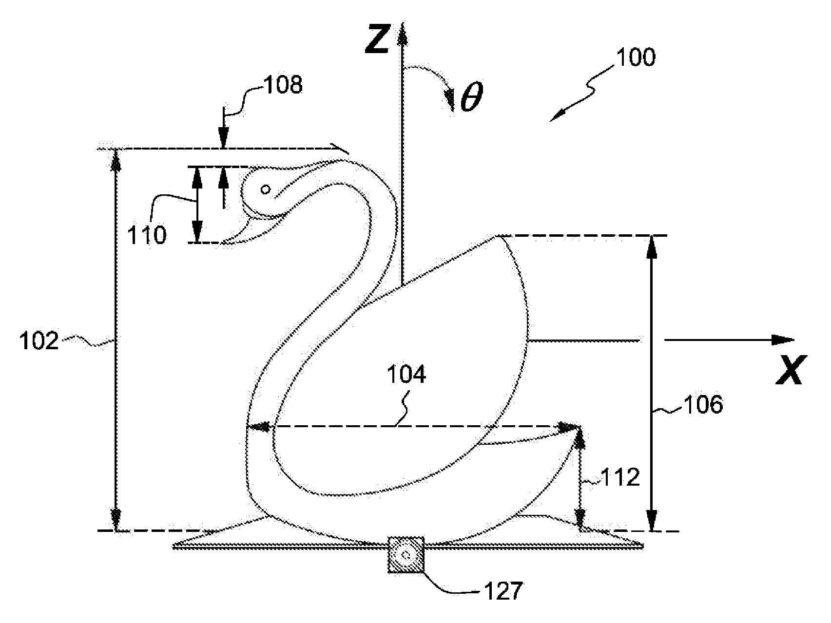
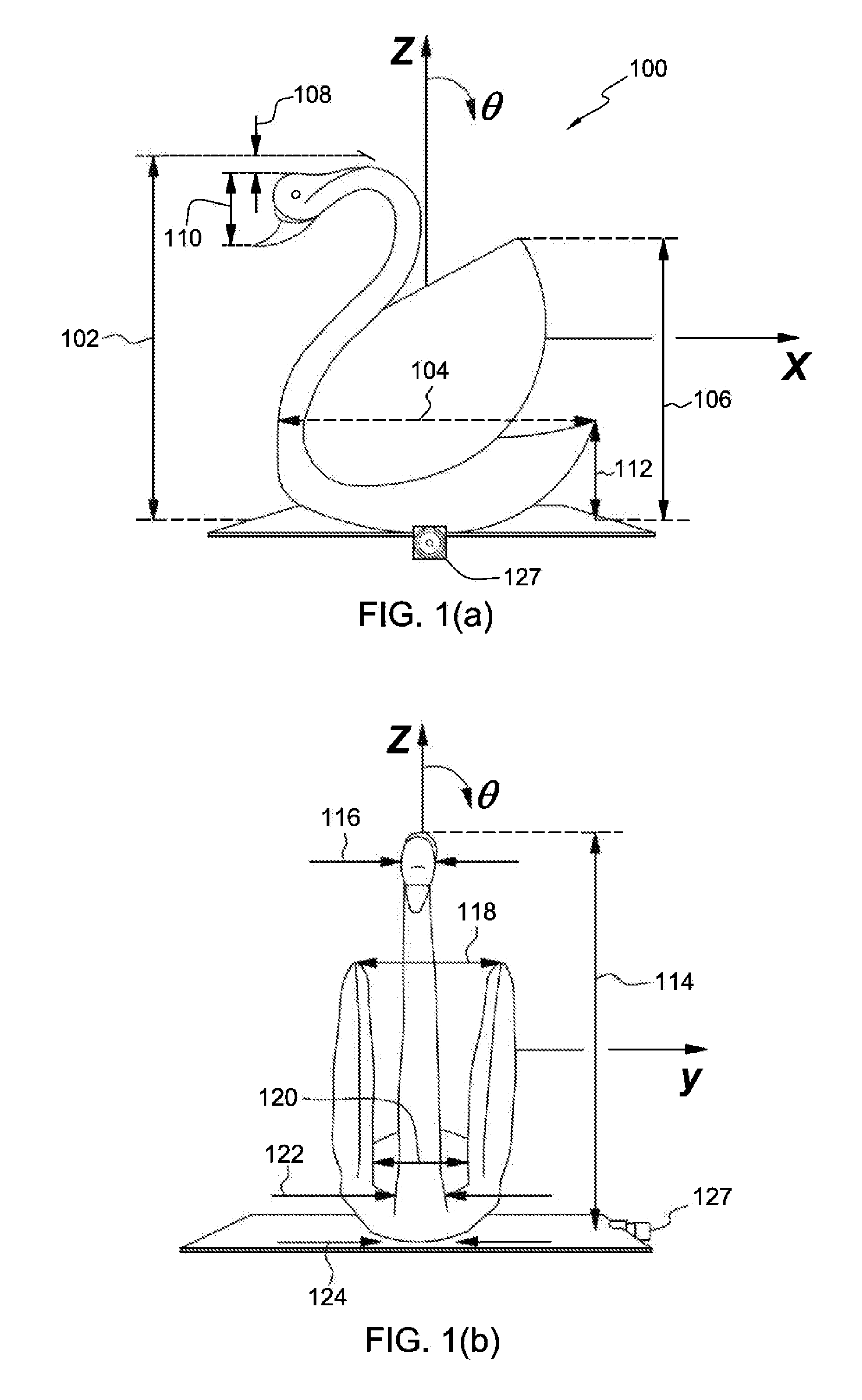
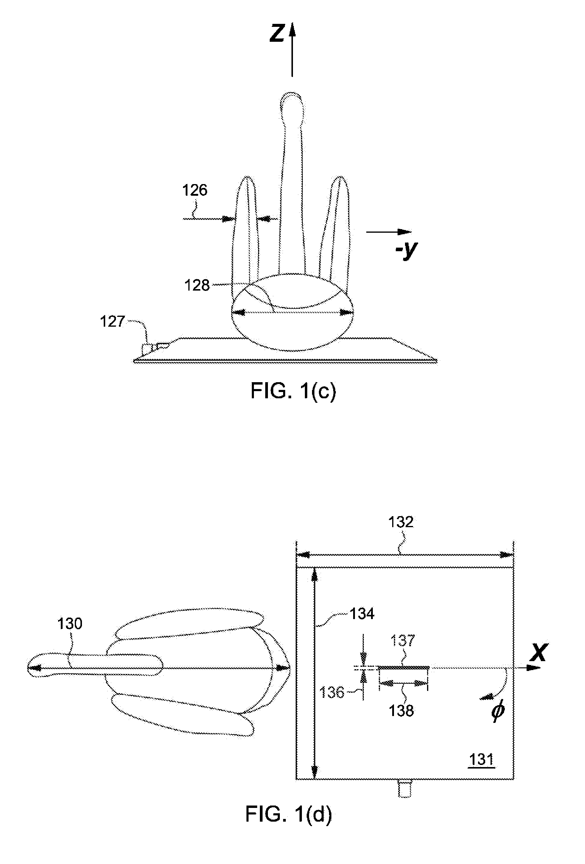
[0021]In this invention, a dielectric antenna (including a Dielectric Resonator Antenna DRA) is integrated with a decoration artwork such as, for example, statue, dummy, idol, animal, and vase. Any dielectric materials with a dielectric constant greater than one, such as crystal and glass, can be used for its design. Crystal and glass wares or artworks are often seen at homes and offices for decoration purposes. With this invention, beautiful crystal and glass wares or artworks can be employed as ant...


PUM


Abstract

An aesthetic dielectric antenna (e.g., a dielectric resonator antenna) includes an aesthetically shaped decoration having at least one dielectric with a dielectric constant of more than one. A waveguide, feedline, probe or other means of excitation is electronically coupled to the dielectric to emit a radiation pattern for carrying analog or digital information.

Description

CROSS-REFERENCE TO RELATED APPLICATIONS[0001]This application claims priority under 35 U.S.C. §119 to U.S. Provisional Application No. 61 / 607,534, filed Mar. 6, 2012, which is herein incorporated by reference in its entirety.BACKGROUND OF THE INVENTIONBackground Information[0002]Due to the rapid development of wireless communications, base station antennas can be easily found in our daily life. Normally, these antennas have a much higher radiation power than mobile-phone antennas. Therefore, people may have psychological concerns if base station antennas are in close proximity to them. As a result, some antennas are deliberately hidden to avoid potential psychological problems.[0003]For example, some cellular towers are camouflaged to blend in with the surroundings by, e.g., painting or adding artificial tree limbs and the like. The antenna tower itself is still conventionally shaped, but simply covered to minimize recognition of the tower by the human eye. These types of solutions ...

Claims


Application Information

Patent Timeline
IPC IPC(8): H01Q9/04
CPCH01Q1/36H01Q9/0485H01Q1/44
Inventor LEUNG, KWOK WAFANG, XIAOSHENGLIM, ENG HOCK
Owner CITY UNIVERSITY OF HONG KONG
Learn More