
Input device and display apparatus

a display device and input device technology, applied in the field of input devices, can solve the problems of frequently occurring position detection errors and output of undesired position data, and achieve the effect of reliable updating of the screen display

Active Publication Date: 2013-09-12
ALPS ALPINE CO LTD
View PDF0 Cites 13 Cited by
  • Summary
  • Abstract
  • Description
  • Claims
  • Application Information

AI Technical Summary

Benefits of technology

The present invention provides an input device with load sensors that can detect position accurately. The device uses a correction algorithm that takes into account the load sensors' positions and the changes in load balance caused by the input. The device also calculates the position coefficients of each load sensor to improve accuracy, and obtains a moving average of the calculation data to remove electric white noise. As a result, the device can reliably update the screen display based on the pressed input position.

Problems solved by technology

In the input device, there is a problem in that position detection errors frequently occur due to the effects of disturbance and noise caused by the input device's own weight and vibration of the panel if there is no processing for the effects and thus undesired position data is output even when there is no input of the operation.

Method used


Image

  • Input device and display apparatus
  • Input device and display apparatus
  • Input device and display apparatus

Examples


Embodiment Construction

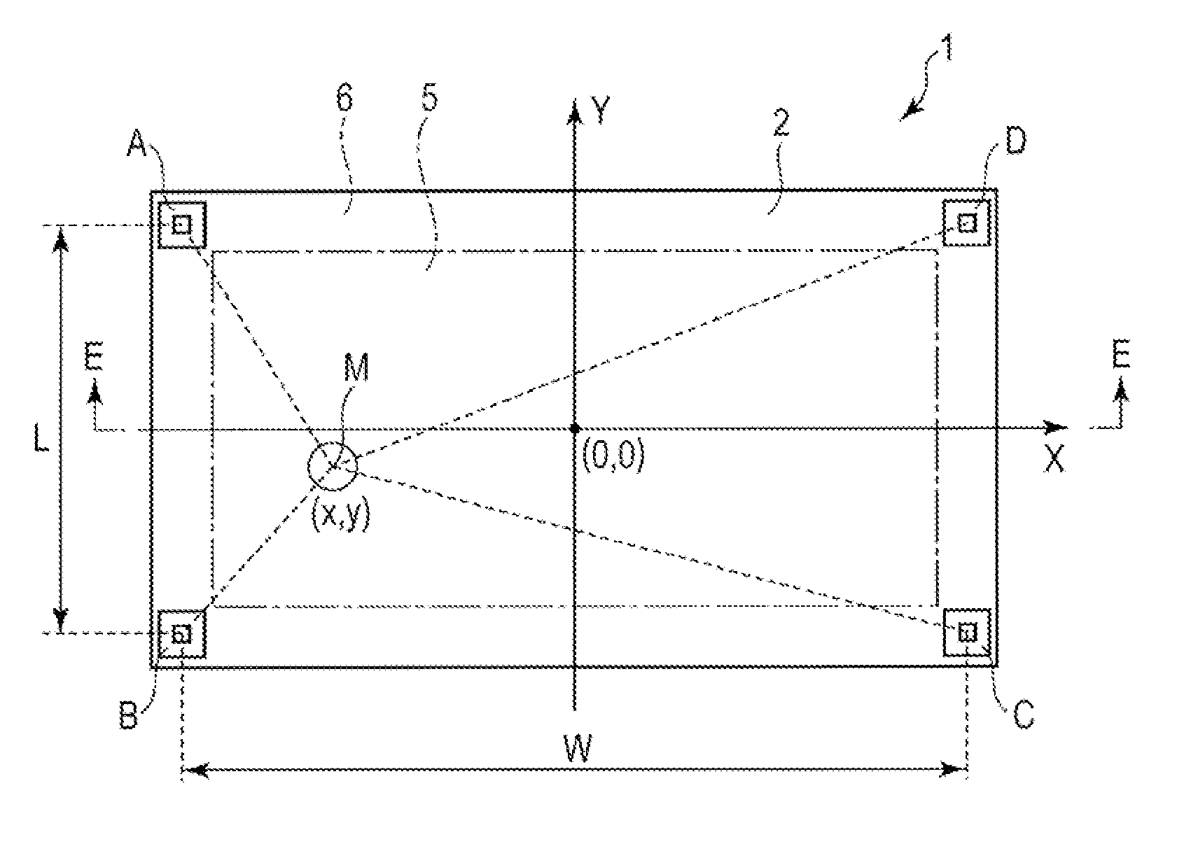
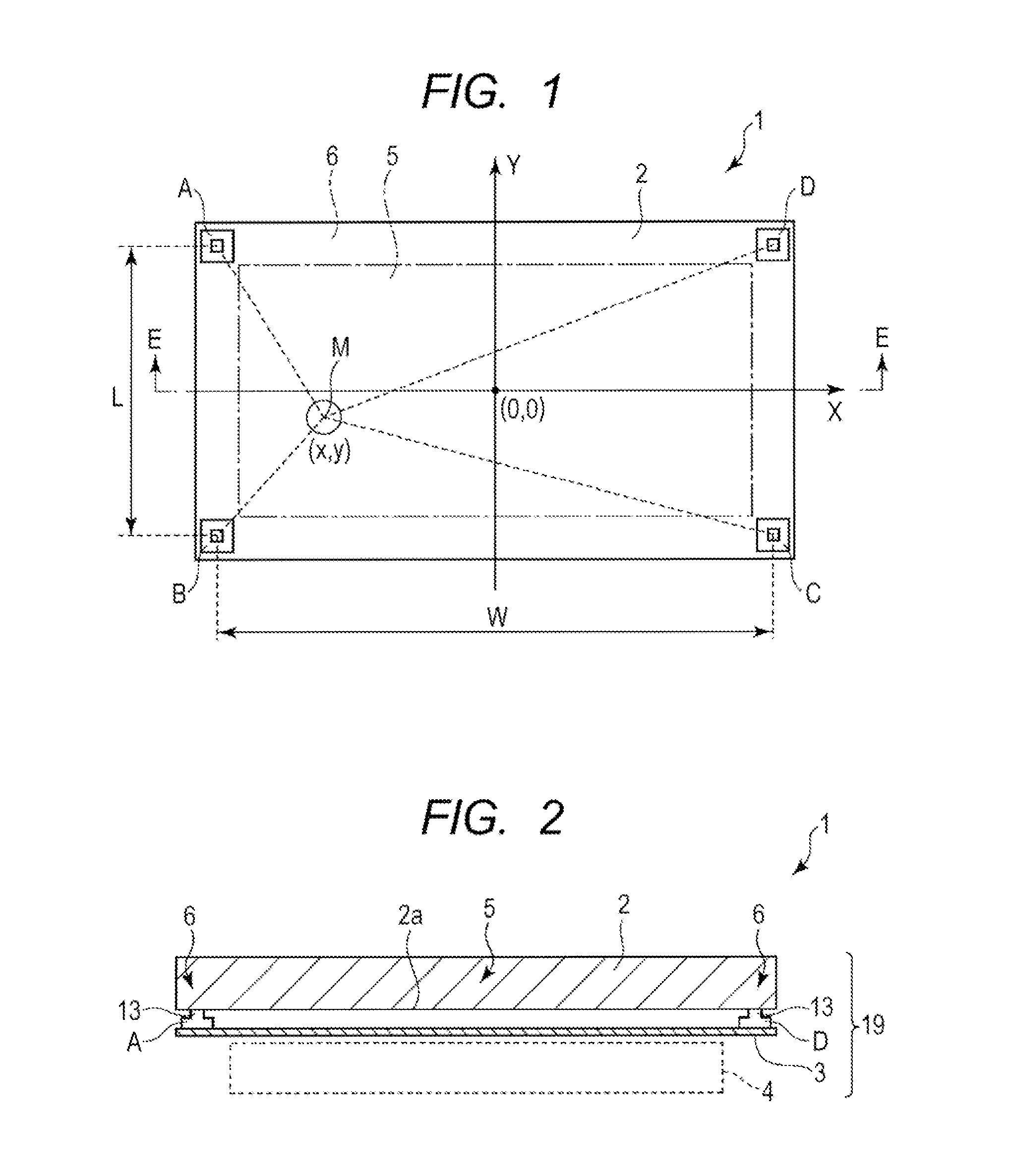
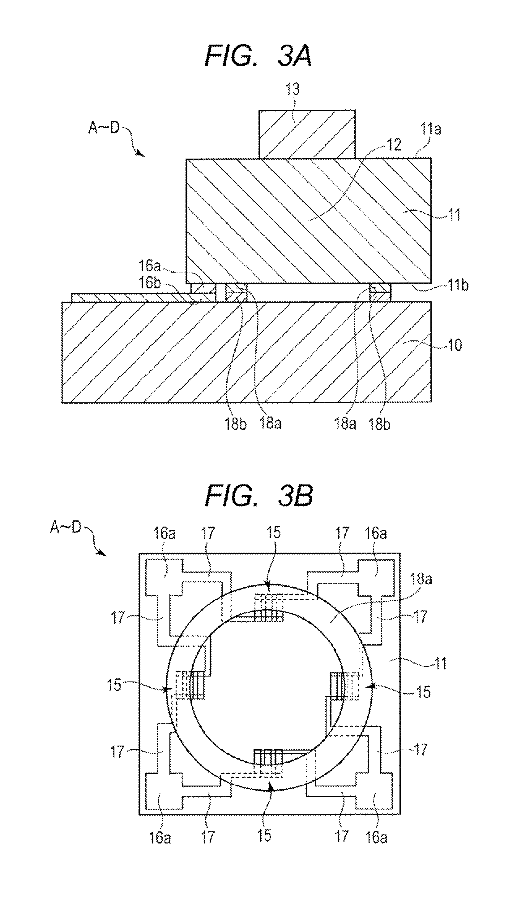
[0028]FIG. 1 is a top plan view schematically illustrating an input device (touch panel) and a display apparatus according to the embodiment. FIG. 2 is a partial vertical cross-sectional view of a part cut along the line E-E shown in FIG. 1 as viewed from the direction of the arrow. FIG. 3A is a partially enlarged vertical cross-sectional view of a load sensor (force sensor) according to the embodiment. FIG. 3B is a backside view of a sensor substrate constituting the load sensor. FIG. 4 is a block diagram of the input device according to the embodiment.

[0029]The input device 1 according to the embodiment (touch panel) includes, as shown in FIGS. 1 and 2, a panel 2 formed of a transparent glass substrate and the like, and plural load sensors (force sensors) A to D disposed under the panel 2.

[0030]Further, in the embodiment, the configuration, in which a liquid crystal display 4 is provided under the input device 1, is a “display apparatus 19”.

[0031]As shown in FIG. 2, the load senso...


PUM


Abstract

There is provided an input device including: means for performing zero point correction on the sensor outputs of the load sensors when an absolute value of an amount of output change of each load sensor is not more than a predetermined threshold a during a certain period of measurement time; means for calculating position data and calculating a total load Z of the load sensors by using the sensor outputs; means for determining that the calculation data pieces are normal when the absolute value |dZ / dt| of the amount of change in the total load Z is not more than the threshold β; means for determining that an input is present in the calculation data pieces when the absolute value |Z| of the total load is not less than the threshold γ; and means for removing a predetermined number of first and last data pieces in the calculation data pieces.

Description

CLAIM OF PRIORITY[0001]This application is a Continuation of international Application No. PCT / JP2011-068515 filed on Aug. 15, 2011, which claims benefit of Japanese Patent Application No. 2010-241313 on Oct. 27, 2010. The entire contents of each application noted above are hereby incorporated by reference.BACKGROUND OF THE INVENTION[0002]1. Field of the Invention[0003]The present invention relates to an input device having a load sensor under a panel, and particularly an algorithm for correcting position detection.[0004]2. Description of the Related Art[0005]There are input devices that have plural load sensors (force sensors) disposed on different positions under the panel so as to detect the input position on the basis of the load balance when the panel surface is pressed. In the input device, there is a problem in that position detection errors frequently occur due to the effects of disturbance and noise caused by the input device's own weight and vibration of the panel if there...

Claims


Application Information

Patent Timeline
IPC IPC(8): G06F3/041
CPCG06F3/0414G06F3/0418G06F3/041G06F3/0488G01L1/205G06F3/016G01L1/18
Inventor YANAGI, SHUJIUMETSU, EIJIISHIZONE, MASAHIKO
Owner ALPS ALPINE CO LTD
Learn More