Image forming apparatus
a technology of forming apparatus and image, which is applied in the direction of electrographic process apparatus, printing, instruments, etc., can solve the problems of affecting the appearance of images on the sheet. , to achieve the effect of suppressing the occurrence of fogging in the edge area and reducing the laser light emission tim
- Summary
- Abstract
- Description
- Claims
- Application Information
AI Technical Summary
Benefits of technology
Problems solved by technology
Method used
Image
Examples
embodiment 1
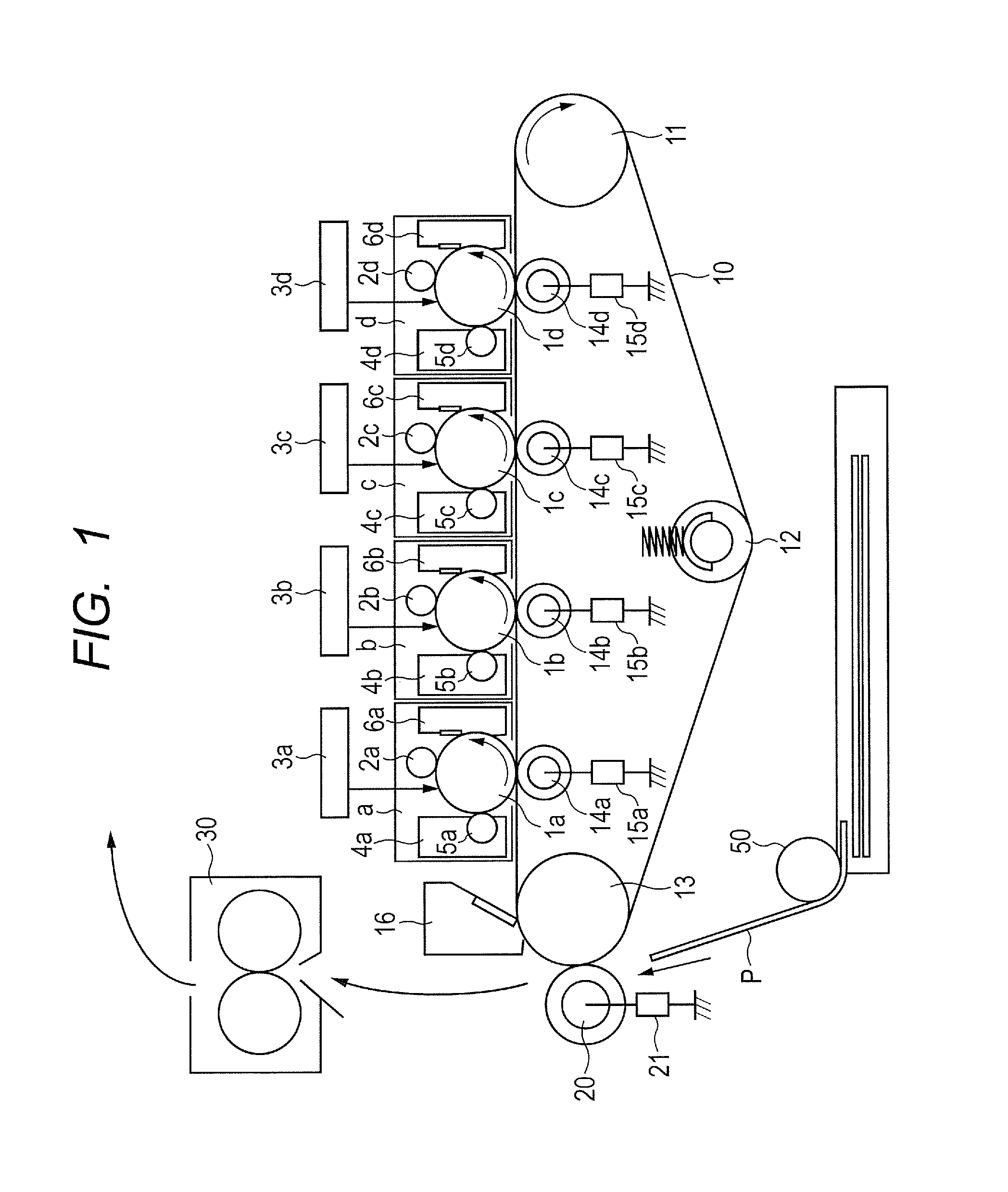
[0027]FIG. 1 is a schematic diagram of a color image forming apparatus. Referring to FIG. 1, the configuration and operation of the image forming apparatus of Embodiment 1 will be described. The image forming apparatus of this embodiment includes first to fourth image forming stations. The first image station (subscript a) is for yellow (Y). The second image station (subscript b) is for magenta (M). The third image station (subscript c) is for cyan (C). The fourth image station (subscript d) is for black (Bk). The subscripts a to d are omitted unless necessary. In this specification, the image forming operation will be described with reference to the first station (Y), which is employed as a typical example.
[0028](Operation of Image Forming Apparatus)
[0029]The image forming apparatus includes an electrophotography photosensitive member (hereinafter, called a photosensitive drum) 1 having a drum shape. The photosensitive drum 1 is rotatably driven in the direction of an arrow (counte...
embodiment 2
[0061]As to the configurational elements of the image forming apparatus applied to Embodiment 2 that are analogous to those of Embodiment 1, the same components are assigned with the same symbols. The description thereof is omitted.
[0062](Characteristics of this Embodiment)
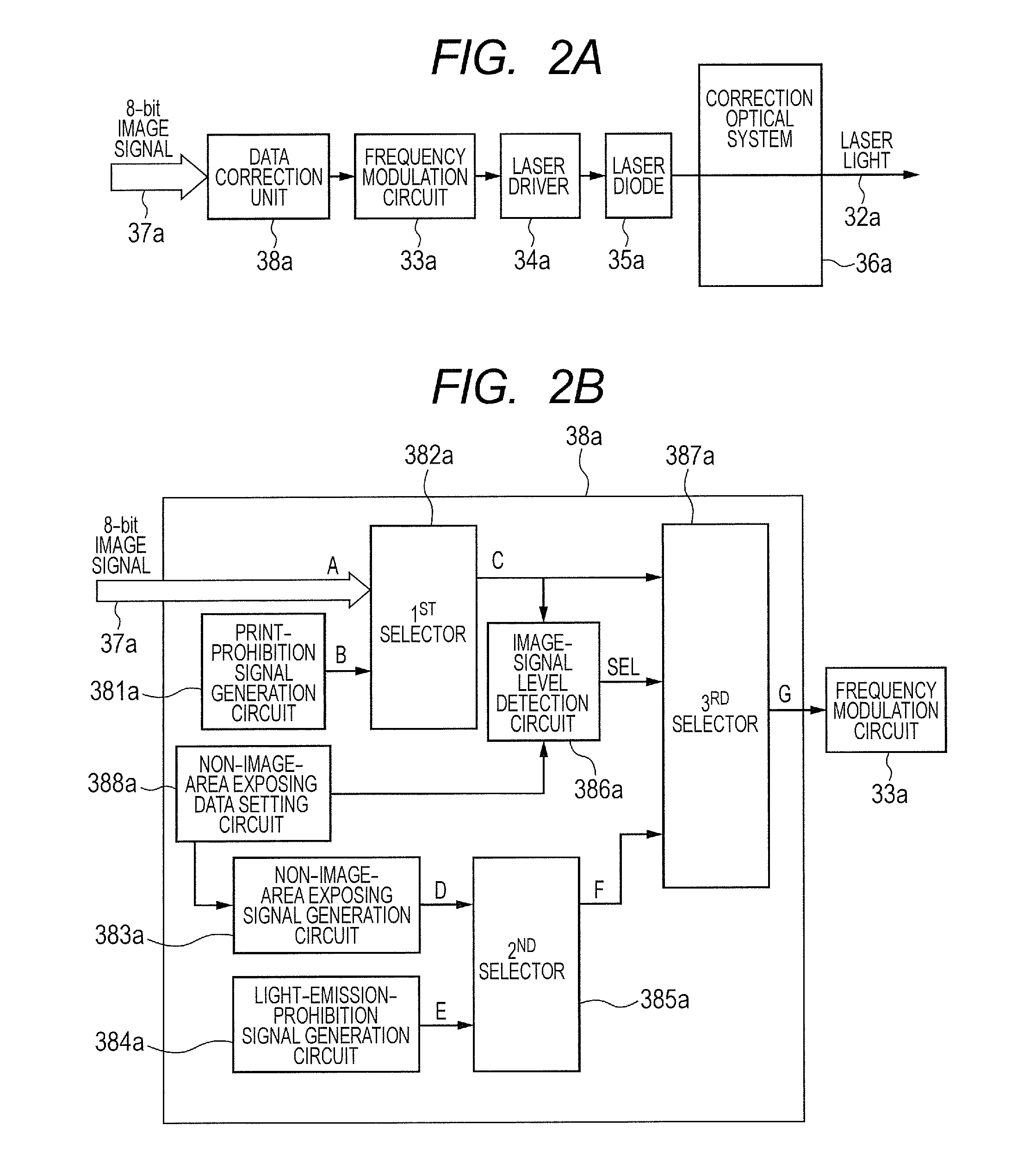
[0063]This embodiment is principally characterized in that the non-image-area exposure region in which weak light emission is performed is within the width of the charged region in the main scanning direction but wider than the maximum width of the sheet possible to feed (maximum width) irrespective of the sheet size. That is, this embodiment is characterized in that the non-image-area exposure region is wider than the sheet size (the sheet length in the case of the sub-scanning direction) of the recording medium (prescribed recording medium) with the maximum size (maximum width) among recording media on which an image can be formed by the image forming apparatus of this embodiment. The control of non-image-area e...
embodiment 3
[0069]As to the configurational elements of the image forming apparatus adopted in this embodiment that are analogous to those of Embodiment 1, the same components are assigned with the same symbols. The description thereof is omitted.
[0070](Characteristics of this Embodiment)
[0071]This embodiment is principally characterized in that control of non-image-area exposure is also performed in light-emission-prohibition regions, such as interpage gaps. Control of non-image-area exposure is analogous to Embodiments 1 and 2. Accordingly, the description is omitted. Here, in a state where, provided that there are a preceding sheet (first recording medium) conveyed previously and a subsequent sheet (second recording medium) conveyed after the preceding sheet and thus the plural recording media are sequentially conveyed, the interpage gap indicates an interval between the trailing edge of the preceding sheet and the leading edge of the subsequent sheet. This embodiment will hereinafter be des...
PUM
 Abstract
Description
Claims
Application Information
 - R&D
- Intellectual Property
- Life Sciences
- Materials
- Tech Scout
- Unparalleled Data Quality
- Higher Quality Content
- 60% Fewer Hallucinations
Browse by: Latest US Patents, China's latest patents, Technical Efficacy Thesaurus, Application Domain, Technology Topic, Popular Technical Reports.
© 2025 PatSnap. All rights reserved.Legal|Privacy policy|Modern Slavery Act Transparency Statement|Sitemap|About US| Contact US: help@patsnap.com


