
Digital camera having multiple image capture systems

Inactive Publication Date: 2013-09-12
APPLE INC
View PDF6 Cites 69 Cited by
  • Summary
  • Abstract
  • Description
  • Claims
  • Application Information

AI Technical Summary

Benefits of technology

The present invention allows for a digital camera system to be mounted in different orientations, including a position that reduces wind resistance and makes the system more compact. This makes it easier to mount on things like helmets or bicycle handlebars. Additionally, the invention includes a reduced power mode that helps conserve power when the camera system is mounted in a way that the user cannot easily see the image display.

Problems solved by technology

However, the HD Hero2 camera includes only a single image capture system, which captures images using an optical axis directed outward from the “front” of the camera.
This can cause excessive wind resistance and presents a high profile that is more susceptible to damage and image artifacts from vibrations in some situations.
Unfortunately, because the accessory receives notifications whenever there is a change in the camera state, power must be continuously supplied to ensure that a notification can be received by the accessory.
This can rapidly deplete the batteries which control the accessory.

Method used


Image

  • Digital camera having multiple image capture systems
  • Digital camera having multiple image capture systems
  • Digital camera having multiple image capture systems

Examples


Embodiment Construction

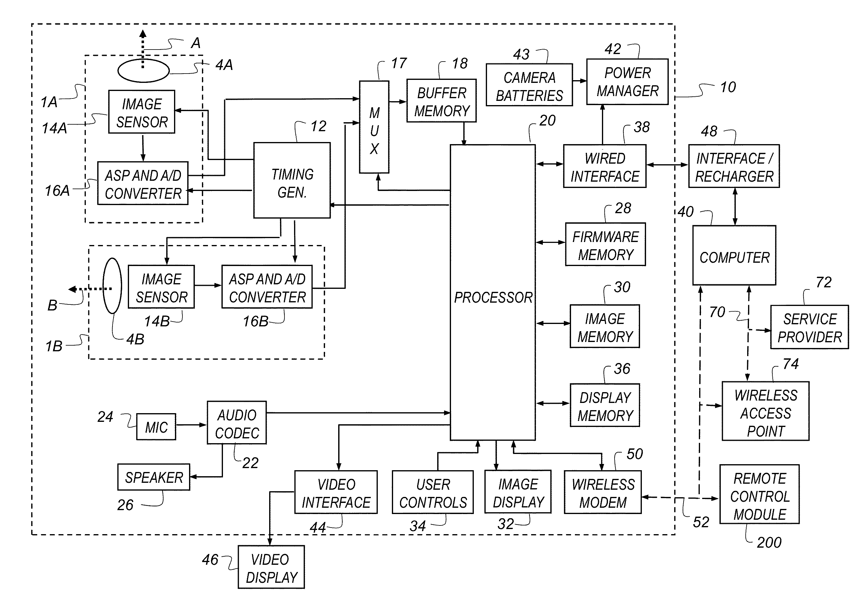
[0036]In the following description, a preferred embodiment of the present invention will be described in terms that would ordinarily be implemented as a software program. Those skilled in the art will readily recognize that the equivalent of such software can also be constructed in hardware. Because image manipulation algorithms and systems are well known, the present description will be directed in particular to algorithms and systems forming part of, or cooperating more directly with, the system and method in accordance with the present invention. Other aspects of such algorithms and systems, and hardware or software for producing and otherwise processing the image signals involved therewith, not specifically shown or described herein, can be selected from such systems, algorithms, components and elements known in the art. Given the system as described according to the invention in the following materials, software not specifically shown, suggested or described herein that is usef...


PUM


Abstract

A digital camera system providing two different image capture systems, comprising a camera body including a first surface having an image display; a second surface opposite to the first surface; a third surface transverse to the first and second surfaces and having a smaller surface area than the first and second surfaces; and a fourth surface opposite to the third surface. A first image capture system has a first optical axis directed outward from the second surface, and a second image capture system has an optical axis directed outward from the third surface. Camera mounts are provided on the fourth and first or second surfaces to facilitate mounting the digital camera system such that either the first optical axis or the second optical axis can be oriented in a substantially horizontal direction.

Description

CROSS-REFERENCE TO RELATED APPLICATIONS[0001]Reference is made to commonly assigned, co-pending U.S. patent application Ser. No.______ (Docket K000702), entitled: “Digital camera system having remote control”, by Karn et al.; and to commonly assigned, co-pending U.S. patent application Ser. No. ______ (Docket K000750), entitled: “Digital camera system low power capture mode”, by Karn et al., each of which is incorporated herein by reference.FIELD OF THE INVENTION[0002]This invention pertains to the field of digital video cameras, and more particularly to a digital camera having multiple image capture systems.BACKGROUND OF THE INVENTION[0003]Digital capture devices, such as digital cameras and camera phones typically capture and store both still digital images and video clips. These digital capture devices typically include a color display which is used to display captured still digital images and video clips. In many situations, these digital capture devices are held by the user, wh...

Claims


Application Information

Patent Timeline
IPC IPC(8): H04N5/76
CPCH04N5/76H04N5/772H04N5/907H04N9/8042H04N9/8205H04N23/45H04N23/661H04N23/651H04N23/667H04N23/633H04N23/632
Inventor CUCCI, MEGAN LYNOLLILA, DAVIDKARN, KEITH STOLLSONG, KI BOKSUGANO, KATSUTOSHI
Owner APPLE INC
Learn More