
Electromagnetic Field Applicator Array with Integral Sensors for Implicit Correction of Mutual Coupling and Mismatch

an electromagnetic field and integral sensor technology, applied in the field of electromagnetic field applicator arrays with integral sensors for implicit correction of mutual coupling and mismatch, can solve the problems of not being able to sense each antenna element, not having the ability to disclose any motivation or ability, and increasing uncertainty of element mismatch, so as to achieve greater accuracy and determine more accurately.

Active Publication Date: 2013-09-12
FOUND OF RES ON INFORMATION TECH & SOC ITIS FOUND
View PDF4 Cites 7 Cited by
  • Summary
  • Abstract
  • Description
  • Claims
  • Application Information

AI Technical Summary

Benefits of technology

The present invention is about improving the consistency and accuracy of radio frequency hyperthermia treatments by measuring the current flow in the antenna elements and using this information to determine the coupling matrix of the array. This allows for self-calibration for each patient and ensures that the actual radiated field is determined. The invention also includes embedded sensors in the antenna to directly measure the current and use it to modify the excitation of each element, taking into account the mutual coupling and mismatch. The invention can determine the mutual coupling matrix even in the presence of variations in source impedance and undefined cable lengths. Overall, the invention enhances consistency and accuracy through assured field excitation.

Problems solved by technology

U.S. Pat. No. 5,867,123 discussed above also excites each element in turn, but does not use this as a means to achieve self-calibration; even if it did, element mismatch would increase uncertainty.
Lee et al, 1992 / 3 includes transmission lines introduced into the antenna panel, but lacks the ability to sense each antenna element individually, and does not disclose any motivation or ability to determine the antenna currents (or fields) due to either direct excitation or mutually coupled excitation.

Method used


Image

  • Electromagnetic Field Applicator Array with Integral Sensors for Implicit Correction of Mutual Coupling and Mismatch
  • Electromagnetic Field Applicator Array with Integral Sensors for Implicit Correction of Mutual Coupling and Mismatch
  • Electromagnetic Field Applicator Array with Integral Sensors for Implicit Correction of Mutual Coupling and Mismatch

Examples


Embodiment Construction

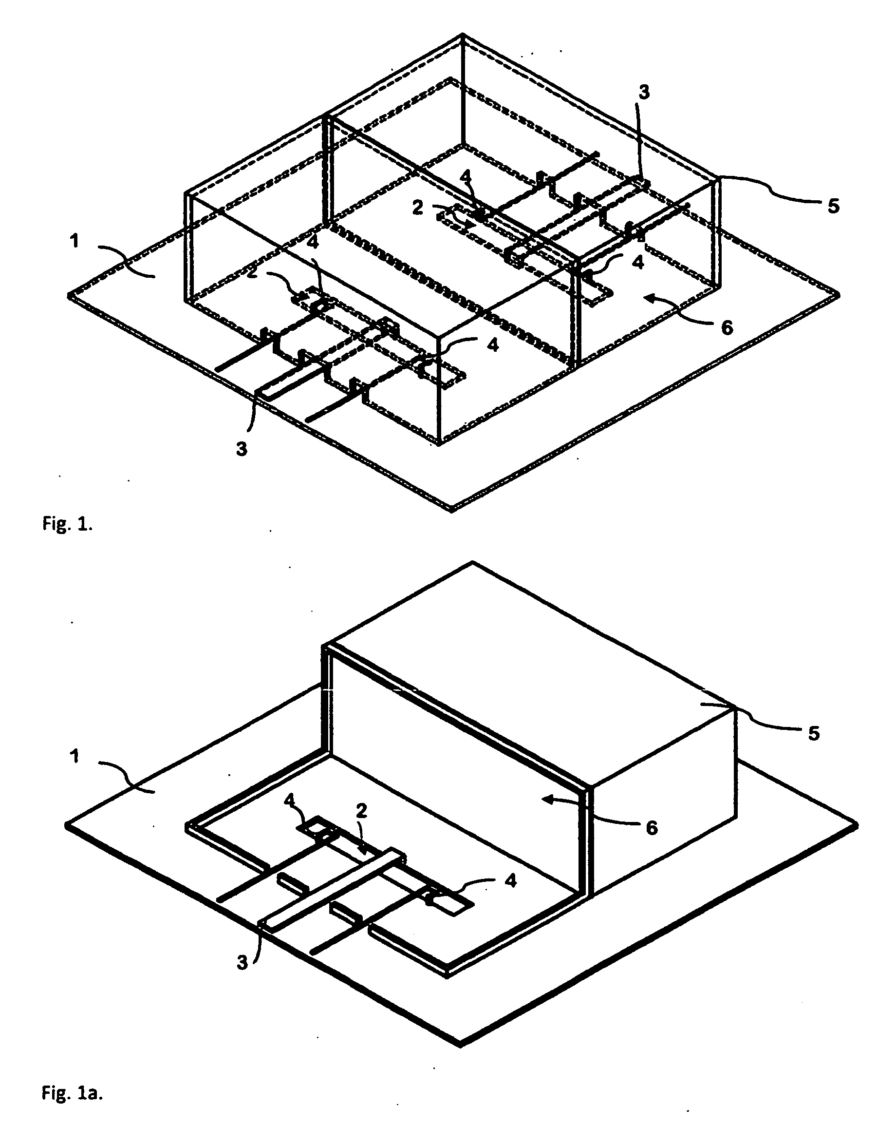
[0033]The preferred embodiment can be described in the context of an RF hyperthermia applicator system, FIG. 5. This hyperthermia applicator system consists of both hardware and a computer control systems and these systems allow enhanced use paradigms that illustrate the utility of the invention.

[0034]The Hyperthermia applicator system illustrated in FIG. 5 takes the form of a ring array applicator made up of electromagnetic field generating elements, FIG. 2, where the electromagnetic field generating elements, FIG. 1, are placed around the body in the vicinity of the region to be heated. It is not always the case that elements need to form an entire ring, but might be placed predominantly on one side of the patient. In this specific array however the E-field vector of all elements should be predominantly aligned in the same direction within the target region, but this is not a requirement in all applications of the system. The region between the applicator and the patient is filled...

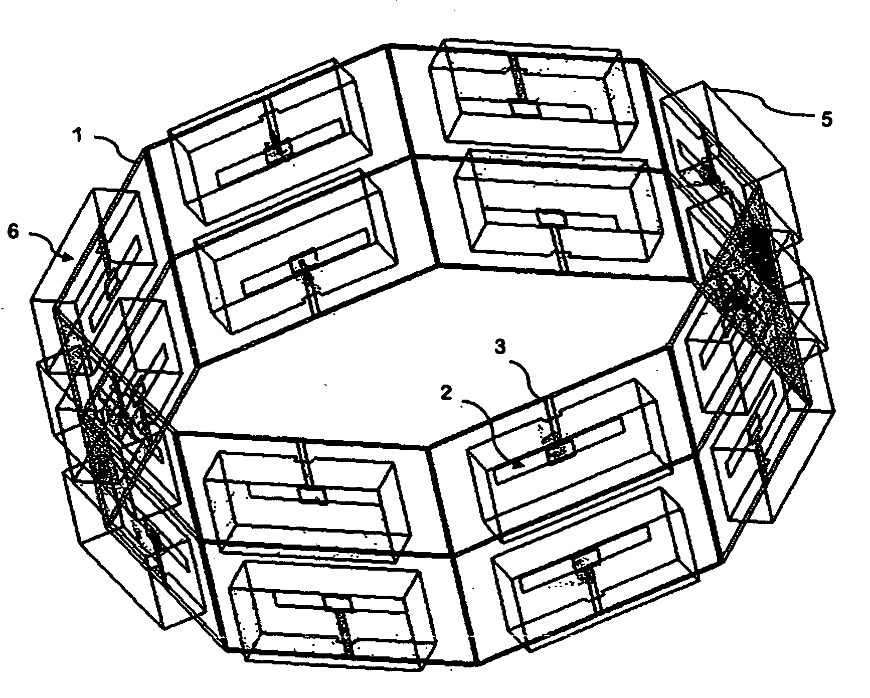
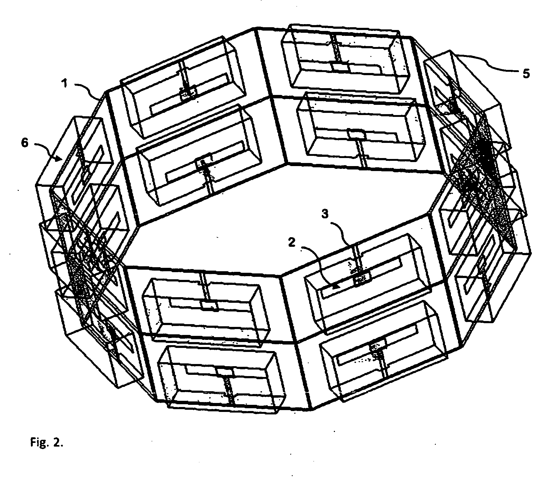

PUM


Abstract

The invention concerns a system for producing. specific field distributions in a defined volume or region. The system comprises an array of electromagnetic field generating elements each with an integrated sensor for measuring the phase and amplitude of the current flowing in a metallic element (antenna or coil) or field in a slot based element, a measurement device to enable measurement of both phase and amplitude of the electrical signals from the sensors with sufficient dynamic range for quantification of the signal, a multi channel radio frequency power source with individually controllable amplitude and phase to excite each of the electromagnetic field generating elements, and a feedback controller enabling controlled adjustment of the amplitude and phase of the radio frequency power source based on the signals from the sensors. The system controls the outputs of a multi channel radio frequency power source such that the current in a metallic or the field in a slot based electromagnetic field generating elements provide the desired electromagnetic field values and the superposition of the fields produced by each electromagnetic field generating element produces said specific electromagnetic field distribution in said defined volume or region. As the signal picked up by each sensor is directly related to the phase and amplitude of the current or field in the associated electromagnetic field generating element and hence the electromagnetic field generated by the array elements, where the current or field measured is the sum of both the applied (from the radio frequency power source) and secondary excitations from mutual coupling and reflections hence the measured value represents the ideal excitation in the absence of mutual coupling, reflections and mismatch. The feedback controller modifies the direct excitation such that the total excitation is the ideal array excitation without coupling or mismatch. The invention implicitly corrects for the coupling and mismatch without explicit knowledge of, and calculation based on, the mutual coupling and mismatch, termed the coupling matrix, such that changes in the coupling matrix due to presence of objects or changes thereof are inherently taken into account. Additionally, by sequentially exciting each element in turn the invention can directly determine the exact mutual coupling matrix of the array even in the presence of variations in source impedance and undefined cable lengths such that initial excitation amplitudes and phases can be calculated to allow rapid adjustment to the desired values. A particular application of interest is in radio frequency hyperthermia applicator systems.

Description

BACKGROUND OF THE INVENTION[0001]This invention relates to systems for creating specific electromagnetic field conditions within specific regions in space, or for focussing electromagnetic energy into dielectric objects with enhanced control.[0002]The ability to create specific electromagnetic field conditions is a core requirement in many medical applications from imaging to therapies. The present invention has applications in both these disciplines, as well as in phased array technology employed for communications and sensing applications.[0003]One application of this invention is the generation of specific field conditions at certain locations in the human body for the purpose of hyperthermia.[0004]The National Cancer Institute of the US National Institutes of Health defines Hyperthermia (also called thermal therapy or thermotherapy) as a type of cancer treatment in which body tissue is exposed to high temperatures (up to 45° C.). Research has shown that high temperatures can dam...

Claims


Application Information

Patent Timeline
Patent Type & Authority Applications(United States)
IPC IPC(8): A61B18/18
CPCA61B18/12A61B18/1815A61B2018/0016A61B18/18A61B2018/00869A61B2018/00892A61N1/403A61B2018/00827
Inventor CAPSTICK, MYLESKUSTER, NIELSKUEHN, SVENNEUFELD, ESRA
Owner FOUND OF RES ON INFORMATION TECH & SOC ITIS FOUND
Learn More