Interior point method for reformulated optimal power flow model

a power flow model and internal point technology, applied in the direction of electric variable regulation, process and machine control, instruments, etc., can solve the problems of inability to understand the basic intuitive properties of the inability to solve contingency analysis of power networks, and the thermal limit of transmission lines as well as the constraints of voltage and electrical stability, etc., to achieve optimal power flow and optimal power flow

Active Publication Date: 2013-09-12
SIEMENS AG
View PDF4 Cites 46 Cited by
  • Summary
  • Abstract
  • Description
  • Claims
  • Application Information

AI Technical Summary

Problems solved by technology

Electricity flowing through an AC network is subject to Kirchhoff's Laws, and transmission lines are subject to thermal limits as well as voltage and electrical stability constraints.
OPF models present challenges even for cutting-edge mathematical programming techniques due to a sheer size of contingency cases that fully couple all network components for all adverse scenarios.
Decoupling presents issues as it is well known that contingency analysis of power networks lacks even the most basic intuitive properties such as monotonicity, in that if tripping a branch results in an infeasible network, then tripping this branch and an extra branch should also be infeasible, but often is not.
Note that the tap choice variables wtk are restricted to be in [0; 1] box but in addition can be restricted to be binary by a Mixed-Integer integrability constraint: wt1kε{0; 1} These constraints implies using an MIP solver and is expensive computationally while providing more responsive transformer control.
From the above presentation it is evident that solving OPF models is a very challenging task.

Method used


Image

  • Interior point method for reformulated optimal power flow model
  • Interior point method for reformulated optimal power flow model
  • Interior point method for reformulated optimal power flow model

Examples


Embodiment Construction

[0070]Exemplary embodiments of the invention as described herein generally include systems and methods for estimating a solution of an optimal power flow model of a smart power grid. Accordingly, while the invention is susceptible to various modifications and alternative forms, specific embodiments thereof are shown by way of example in the drawings and will herein be described in detail. It should be understood, however, that there is no intent to limit the invention to the particular forms disclosed, but on the contrary, the invention is to cover all modifications, equivalents, and alternatives falling within the spirit and scope of the invention.

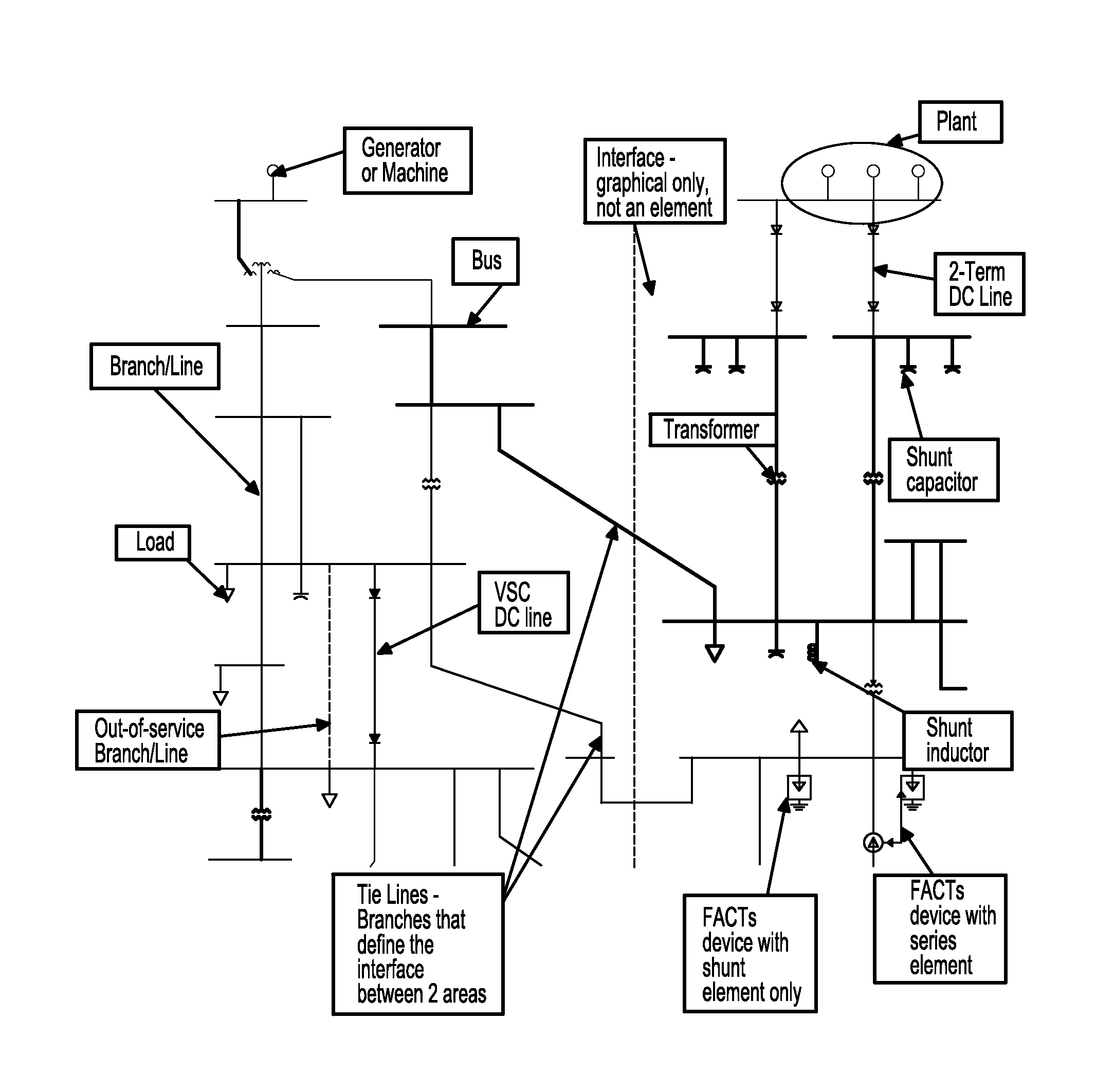
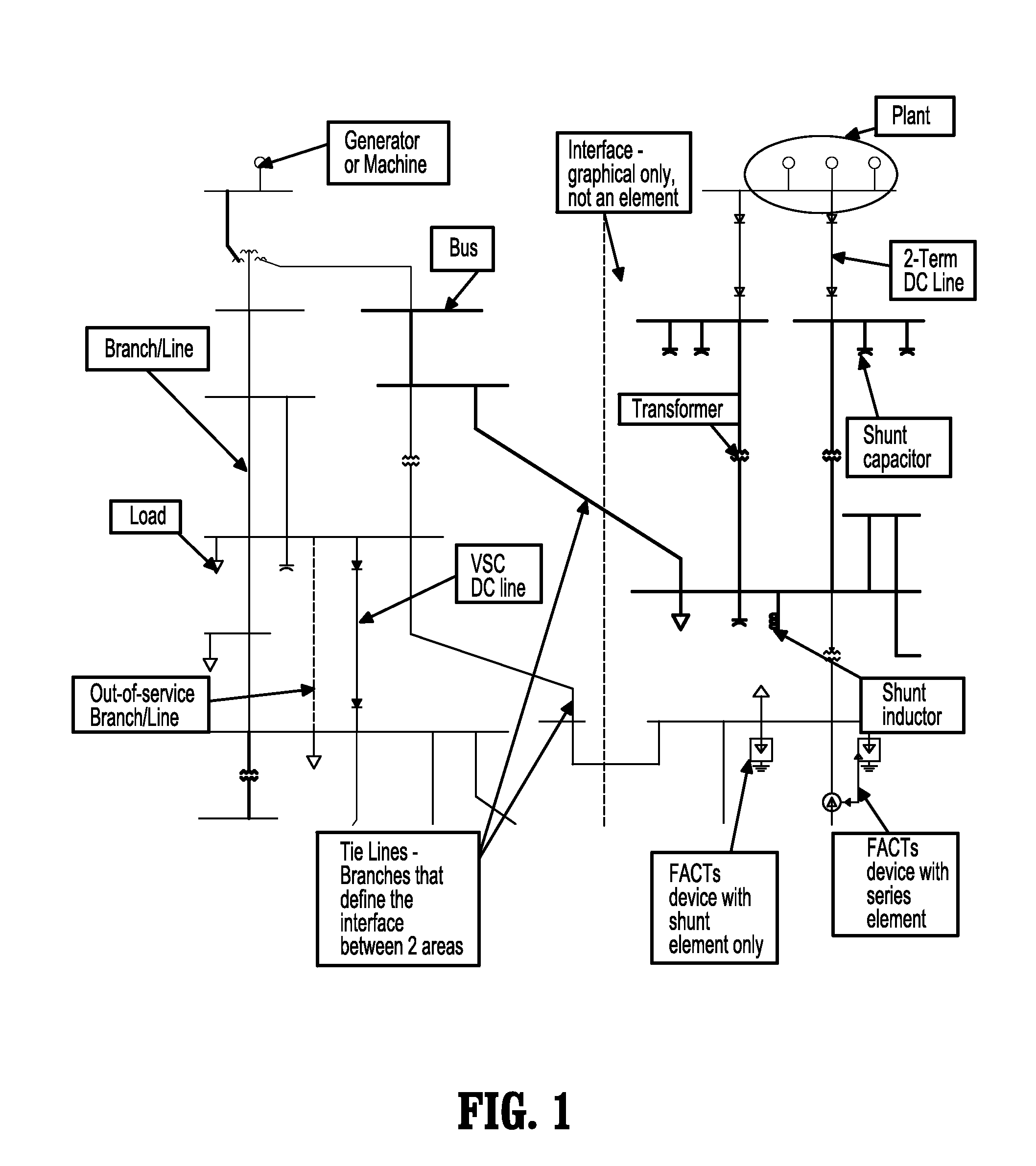
[0071]An optimal power flow (OPF) model seeks to produce an optimal power flow solution that balances generation / consumption for all buses with power distribution across all connected branches such that the overall system state, as measured by underlying physical parameters including voltages and phase angles, is feasible and safe. A base...


PUM


Abstract

A method for approximating an optimal power flow of a smart electric power grid includes providing a cost function that models a smart electric power grid having buses connected by branches, deriving a set of linear equations that minimize the cost function subject to constraints from an expression of an extremum of the cost function with respect to all arguments, reducing a dimension of the linear equations by solving for a subset of the linear equations, re-organizing the reduced dimension linear equations into primal and dual parts, and decomposing the re-organized reduced dimensional linear equations into two systems of block matrix equations which can be solved by a series of back substitutions. A solution of the two systems of block matrix equations yields conditions for a lowest cost per kilowatthour delivered through the smart electric power grid.

Description

TECHNICAL FIELD[0001]This disclosure is directed to methods of analyzing and modeling electric power grids, in particular smart grids.DISCUSSION OF THE RELATED ART[0002]An Optimal Power Flow (OPF) model of an electric power network is a model whose solution provides the conditions which give the lowest cost per kilowatthour delivered. Electricity flowing through an AC network is subject to Kirchhoff's Laws, and transmission lines are subject to thermal limits as well as voltage and electrical stability constraints. An OPF model should be capable to quickly and efficiently analyze an electric power network and yield a feasible power flow solution under a wide variety of adverse conditions and determine the most efficient set of actions to take.[0003]OPF models present challenges even for cutting-edge mathematical programming techniques due to a sheer size of contingency cases that fully couple all network components for all adverse scenarios. Decoupling presents issues as it is well ...

Claims


Application Information

Patent Timeline
Patent Type & Authority Applications(United States)
IPC IPC(8): G05F5/00
CPCG06Q10/04Y02B70/3225Y04S20/222H02J2310/64H02J2203/20H02J3/14Y04S50/10
Inventor LEGBEDJI, MOTTO ALEXISDUZGUN, RUKENAKROTIRIANAKIS, IOANNISCHAKRABORTY, AMIT
Owner SIEMENS AG
Why Eureka
Try Eureka