Permanent electrical contact applicable to the web of rails and the like

a permanent electrical contact and rail connection technology, applied in the manufacture of contact members, railway tracks, rivets, etc., can solve the problems of high copper cost, high cost, and consequent risks of interstitial galvanic corrosion in the contact area between the aluminium connector and the contact bush in copper, and achieve the effect of low cost and low cos

Active Publication Date: 2013-09-19
CEMBRE
View PDF7 Cites 11 Cited by
  • Summary
  • Abstract
  • Description
  • Claims
  • Application Information

AI Technical Summary

Benefits of technology

[0014]The contact bush and permanent electrical contact thus configured make it possible to obtain the specific advantages of a bi-metal contact (no difference of galvanic potential in the area of contact between the cable terminal and the terminal) with low costs and with mechanical resistance suitable for applications subject to strong vibrations.
[0015]Moreover, the use of a contact bush consisting of a multilayer tubular body manufactured through drawing or co-extrusion and subsequent definitive shaping allows a production of the bush and of the permanent electrical contact on a large scale with low costs and with a close and resistant joining between the layers themselves.

Problems solved by technology

However, on account of the significant increase in the cost of copper and consequent frequent theft of conductors made from such metal, over recent years the use of electric conductors and connectors (so-called cable terminals) in aluminium has increased, the use of which however entails exposure to the environment of metals with different galvanic potential, such as copper and aluminium, with consequent risks of interstitial galvanic corrosion in the contact area between the aluminium connector and the contact bush in copper.
Such solution, while resolving the problem of interstitial corrosion of the cable terminal in a satisfactory manner, is not without drawbacks.
The manufacturing process of the single parts in aluminium and copper and their subsequent joining by welding is, on the one hand, complex and costly and, on the other, is not able to obtain a sufficiently reliable and resistant copper-aluminium connection for applications in which the connectors are subject to vibrations.

Method used


Image

  • Permanent electrical contact applicable to the web of rails and the like
  • Permanent electrical contact applicable to the web of rails and the like
  • Permanent electrical contact applicable to the web of rails and the like

Examples


Embodiment Construction

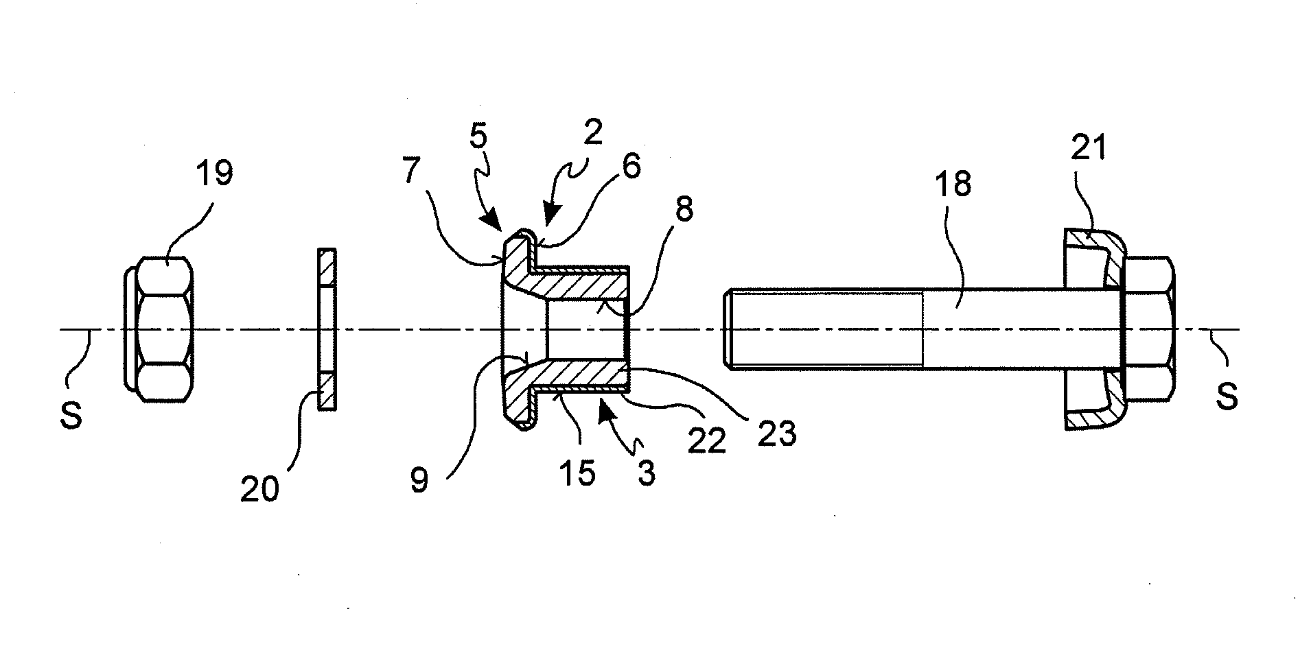
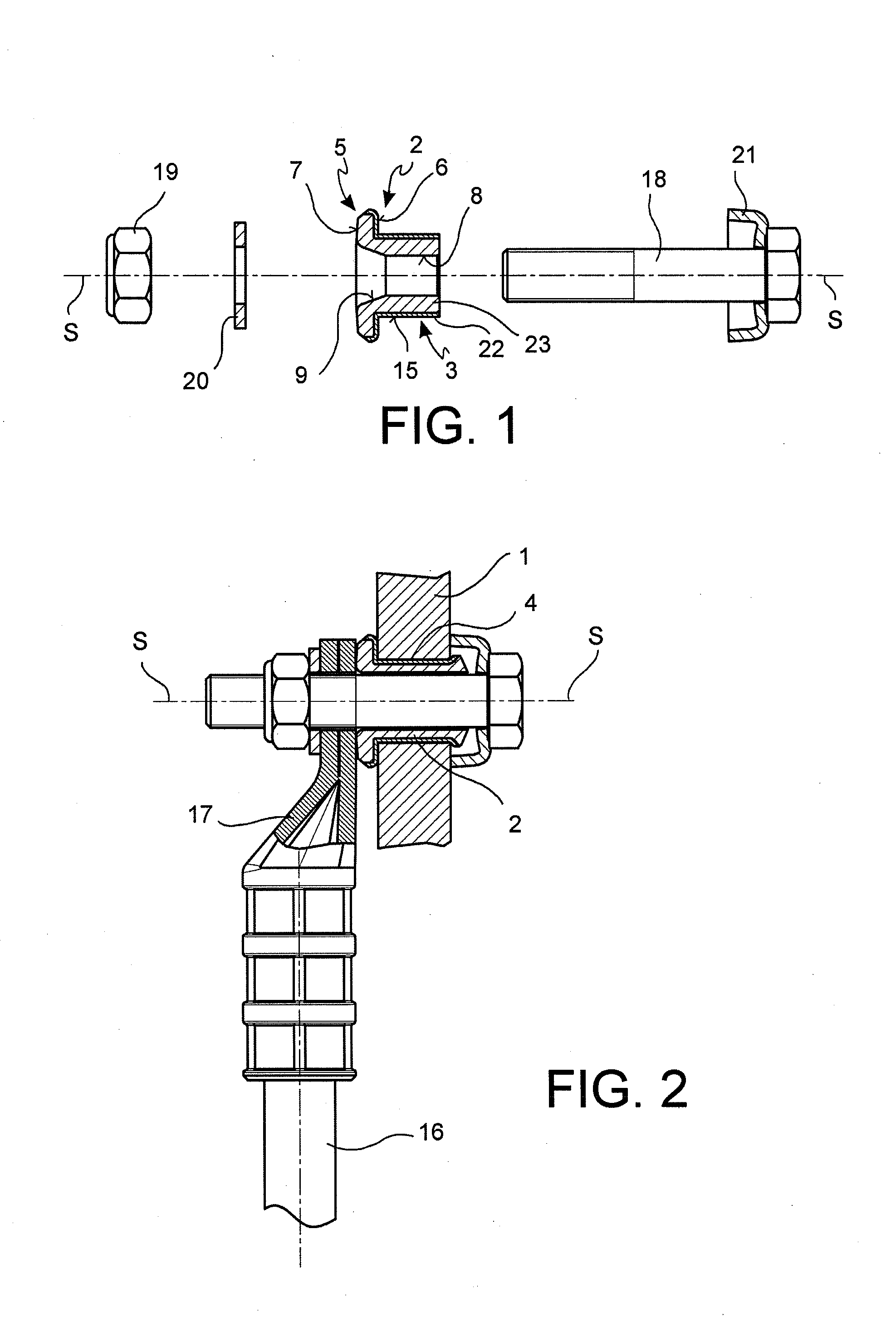
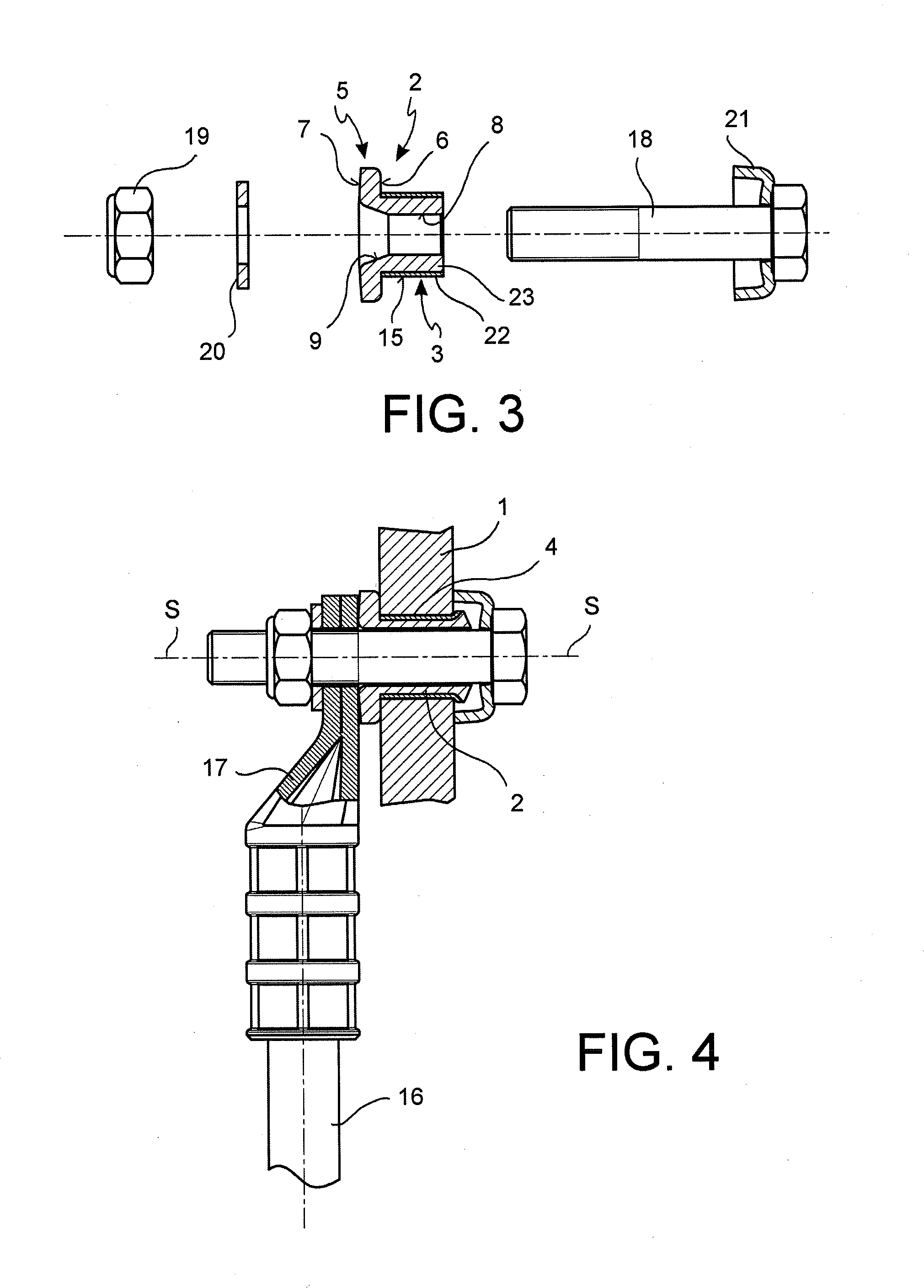
[0027]With reference to the figures, a permanent electrical contact applicable to the web 1 of a rail or the like comprises a contact bush 2 which is made from electrically conductive material and has a tubular stem 3, possibly cylindrical, suitable for inserting in a hole 4 made on the web 1 or flange of a rail. The stem 3 projects and extends in an axial direction S from a flange-shaped head 5 of the bush 2.

[0028]The flange-shaped head 5 is radially widened in relation to the stem 3 and forms an abutment surface 6 facing in the direction of the stem 3 and suitable for abutting against the portion of the web 1 which surrounds the hole 4, when the stem 3 is inserted in the hole 4. The head 5 of the bush 2 forms in addition a front contact surface 7 opposite the abutment surface 6 and facing away from the stem 3.

[0029]The bush 2 forms an axial through hole 8 having a widening 9 at the head 5 for the introduction of a lubricant substance and to prevent unwanted deformations of the hea...


PUM

PropertyMeasurementUnit
thicknessesaaaaaaaaaa
electrically conductiveaaaaaaaaaa

Abstract

A permanent electrical contact applicable to the web of rails. The contact comprises a bush in electrically conductive material having a tubular stem suitable for inserting in a hole in the web of a rail, a flanged head radially widened compared to the stem and suitable for engaging in abutment with a portion surrounding the hole, and an axial through hole in which a punch can be inserted to expand the tubular stem radially and join a radially outer surface of the stem closely with the hole. At least a portion of the outer surface of the stem is substantially made of a first conductive metal and at least a portion of the flanged head is substantially made of a second conductive metal different from the first conductive metal.

Description

BACKGROUND OF THE INVENTION[0001]1. Field of the Invention[0002]The present invention relates to a permanent electrical contact applicable to the web or flange of rails and the like.[0003]2. Description of the Related Art[0004]As known, permanent electrical contacts for the electrical connection of sections of rail are required to have contact characteristics which reduce contact resistances and need to be structurally simple and robust. To such purpose, it is known to make permanent electrical contacts applicable to the web of a rail, by means of a bush in electrically conductive material having a cylindrical stem insertable in a hole made in the web of the rail and a flanged head suitable for engaging in abutment with the portion of rail surrounding the hole, wherein the bush has an axial through hole into which a punch can be inserted to generate a radial expansion of the cylindrical stem against the hole in the rail. Given its excellent mechanical characteristics (plastic deform...

Claims


Application Information

Patent Timeline
Patent Type & Authority Applications(United States)
IPC IPC(8): H01R4/64B21D19/08
CPCB21D19/08H01R4/64H01R4/06H01R4/62B21K1/60B21D39/08B21J15/04B21J15/043H01R43/16E01B26/005
Inventor BAREZZANI, GUALTIERO
Owner CEMBRE
Why Eureka
Try Eureka