Generator

Active Publication Date: 2013-09-19
SIEMENS GAMESA RENEWABLE ENERGY AS
View PDF8 Cites 4 Cited by
  • Summary
  • Abstract
  • Description
  • Claims
  • Application Information

AI Technical Summary

Benefits of technology

The technical effect of this patent text is to improve the mechanical stability of a generator.

Problems solved by technology

Generators such as used in wind turbines have to withstand high mechanical loads during operation.
Particularly, large-scaled generators have to encounter huge axial and / or radial forces during operation, which forces are challenging for the generator support structure, i.e. respective support structures of the rotor and / or the stator in the shape of respective rotor end plates and / or stator end plates.
Thereby, a concrete problem is the maintenance of a constant air-gap between the rotor and the stator.

Method used


Image

  • Generator
  • Generator
  • Generator

Examples


Embodiment Construction

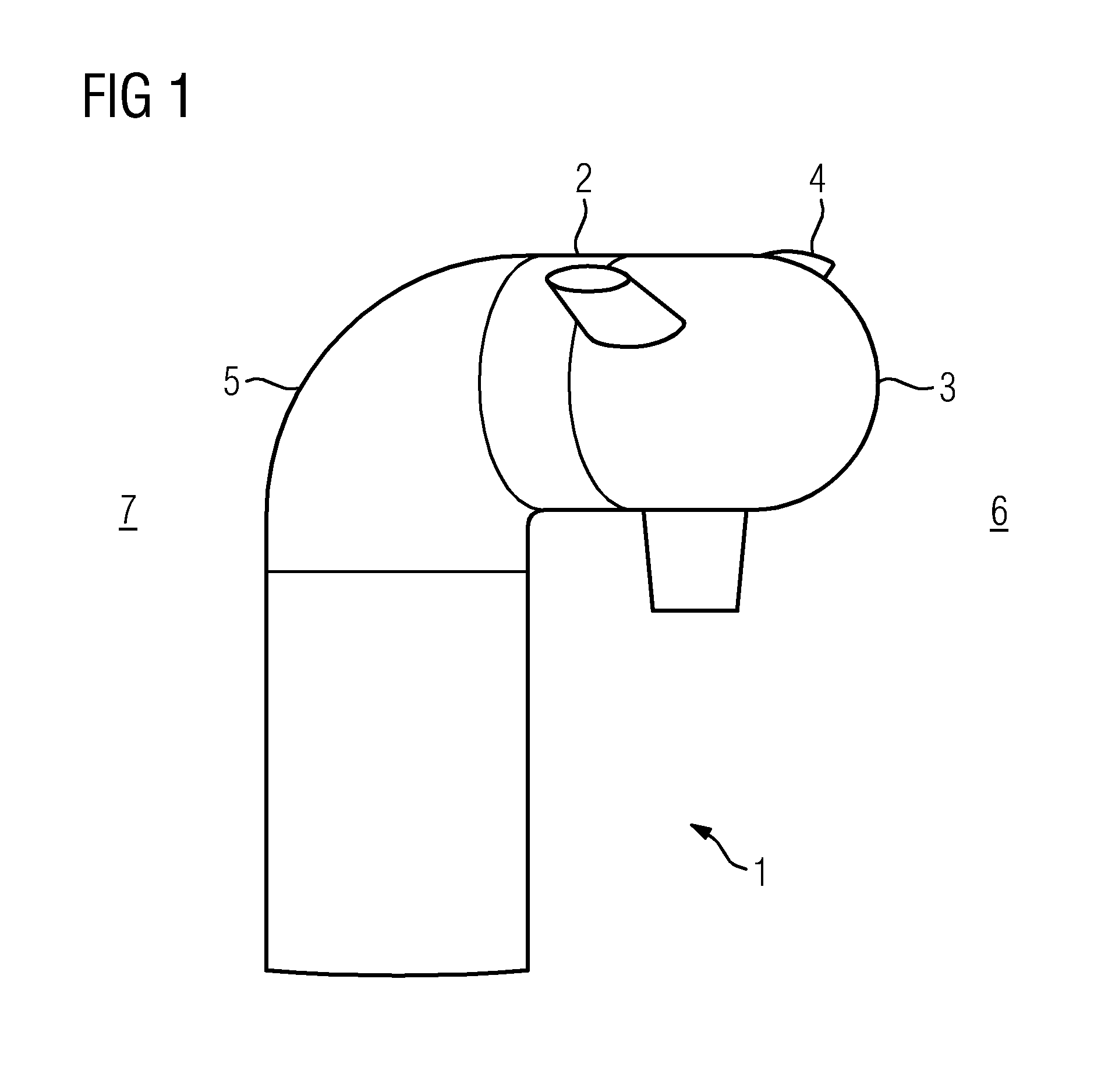
[0033]FIG. 1 shows a principle partial view of a wind turbine 1. The wind turbine 1 may be applicable for offshore applications. The wind turbine 1 is a direct drive wind turbine 1, i.e. the generator 2 of the wind turbine 1 is directly connected to the rotor hub 3 having respective rotor blades 4 attached thereto. Thus, the generator 2 is disposed between a structural component 5 of the wind turbine construction and the rotor hub 3. The structural component 5 may be a so called bedframe or the like. Hence, the generator 2 has one face side oriented towards the drive end 6, i.e. the side of the rotor hub 3 of the wind turbine 1, and one face side oriented towards the non-drive end 7 of the wind turbine construction, i.e. the side of the structural component 5 of the wind turbine construction.

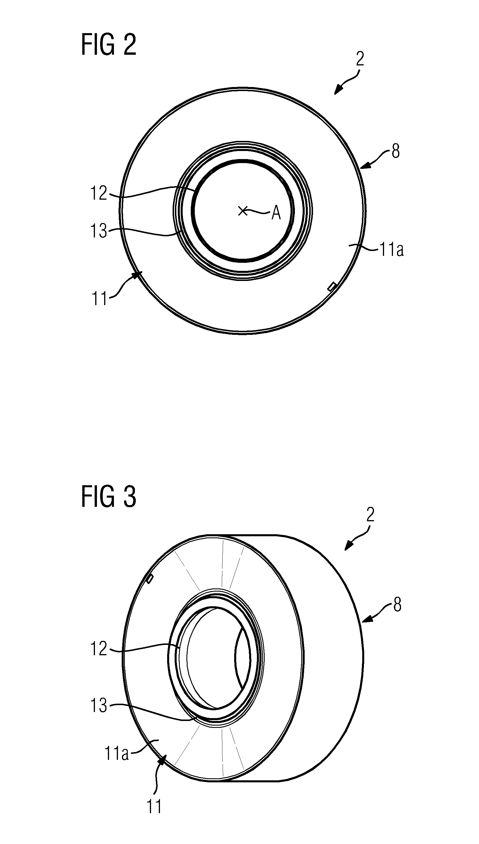
[0034]FIG. 2 shows an axial view at the front side of a generator 2 according to an exemplary embodiment. The front side of the generator 2 refers to the face side of the generator 2 which is or...


PUM


Abstract

A generator, particularly for a wind turbine, having a rotor and a stator is provided. The rotor includes at least one disc-like shaped rotor end plate supporting the rotor and the stator includes at least one disc-like shaped stator end plate supporting the stator, wherein the at least one rotor end plate and / or the at least one stator end plate at least partially extends tilted relative to the centre axis of the generator.

Description

CROSS REFERENCE TO RELATED APPLICATIONS[0001]This application claims priority of European Patent Office application No. 11183806.6 EP filed Oct. 4, 2011. All of the applications are incorporated by reference herein in their entirety.FIELD OF INVENTION[0002]A generator, particularly for a wind turbine, having a rotor and a stator, is provided. The rotor comprises at least one disc-like shaped rotor end plate supporting the rotor and the stator comprises at least one disc-like shaped stator end plate supporting the stator.BACKGROUND OF INVENTION[0003]Generators such as used in wind turbines have to withstand high mechanical loads during operation. Particularly, large-scaled generators have to encounter huge axial and / or radial forces during operation, which forces are challenging for the generator support structure, i.e. respective support structures of the rotor and / or the stator in the shape of respective rotor end plates and / or stator end plates. Thereby, a concrete problem is the ...

Claims


Application Information

Patent Timeline
IPC IPC(8): H02K5/22
CPCF03D1/003H02K1/187H02K1/2786Y02E10/725H02K7/085H02K7/1838H02K5/22H02K1/28F03D80/50Y02E10/72H02K1/2791H02K5/15
Inventor BOOTH, JAMES KENNETHERIKSEN, UFFENIELSEN, JACOB BLACH
Owner SIEMENS GAMESA RENEWABLE ENERGY AS
Why Eureka
Try Eureka