

Solar cell interconnector and manufacturing method thereof
- Summary
- Abstract
- Description
- Claims
- Application Information
AI Technical Summary
Benefits of technology
Problems solved by technology
Method used
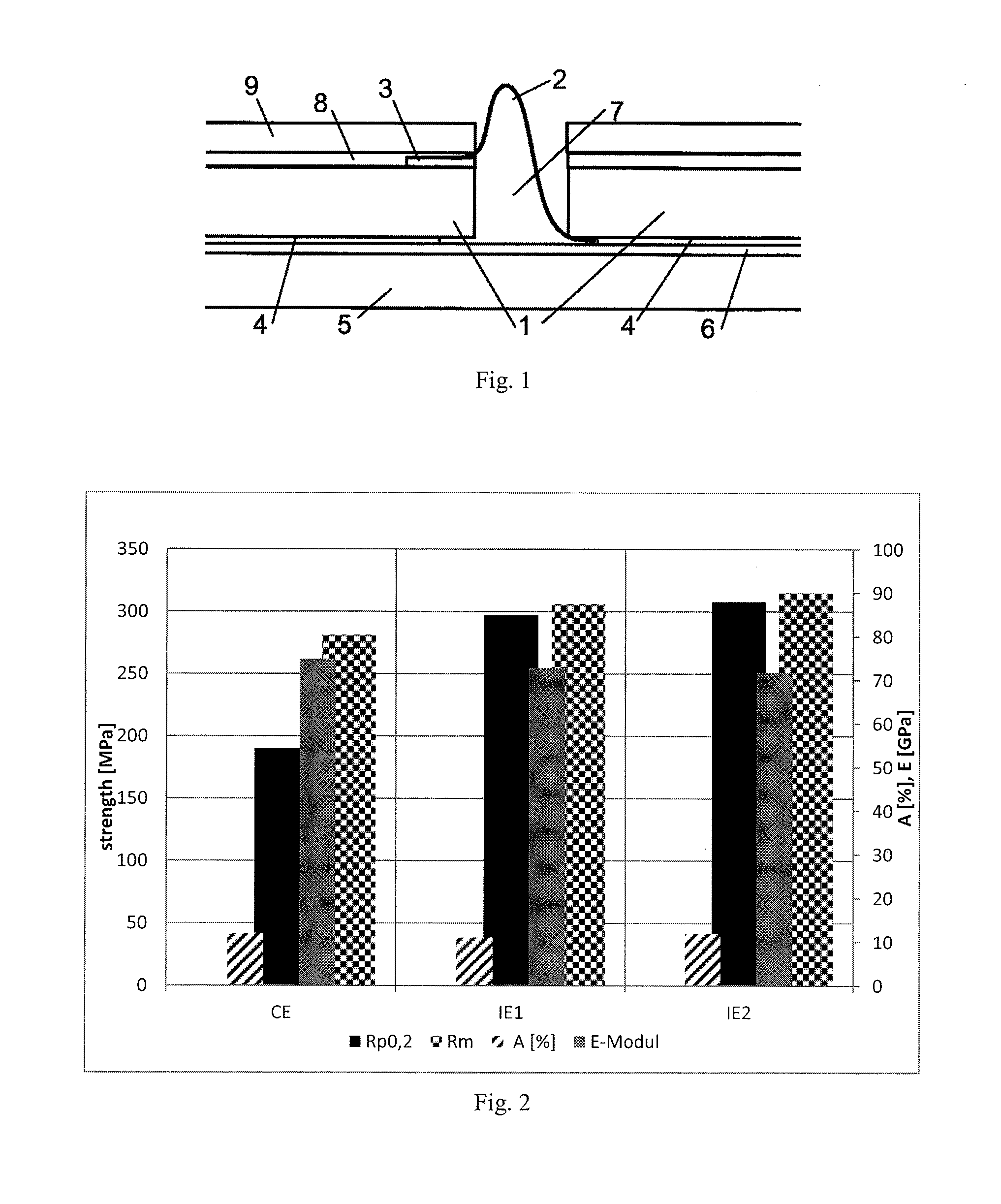
Image

Examples
examples
1. Preparation of Examples
[0157]The comparative and inventive examples were prepared as follows:
example ie1
b) Inventive Example IE1
[0159]An AISc0.6Zr0.3 alloy was manufactured by melting of commercially available pure AI together with the required amount of AISc2 master and AlZr5 master alloys at about 900° C. to dissolve (by diffusion) safely all AI3Sc and Al3Zr dispersoids (AI3Sc has a nominal melting temperature of 1320° C., Al3Zr has a nominal melting temperature of 1580° C.). In order to keep both alloying elements for further processing in solid solution in the Al matrix very fast cooling to room temperature melt-spin rapid solidification was used: The molten material is cast through a tiny nozzle on a fast rotating water cooled Cu-drum which immediately solidifies and separates as an endless 50-100 μm thick ribbon from this drum. The estimated cooling velocity is about 10 000-100 000 K / sec. The endless ribbon material was chopped by a rotating knife. The resulting flakes were then further processed by putting the flakes into a sealed heatable recipient where a vacuum-degassing at ...
example ie2
c) Inventive Example IE2
[0160]An AlSc0.6Zr0.3Yb0.15 alloy was manufactured by melting of commercially available pure AI together with the required amount of an AISc2 master, AIYb2 master and AIZr5 master alloys at about 900° C. to dissolve (by diffusion) safely all Al3Sc, Al3Yb and Al3Zr dispersoids (Al3Sc has a nominal melting temperature of 1320° C., Al3Yb has a nominal melting temperature of 980° C., Al3Zr has a nominal melting temperature of 1580° C.). In order to keep the 3 alloying elements for further processing in solid solution in the Al matrix very fast cooling to room temperature by the melt-spin rapid solidification technology was used: The molten material was cast through a tiny nozzle on a fast rotating water cooled Cu-drum which immediately solidified and separated as an endless 50-100 μm thick ribbon from this drum. The estimated cooling velocity is about 10 000-100 000 K / sec. The endless ribbon material was chopped by a rotating knife. The resulting flakes were then...
PUM
| Property | Measurement | Unit |
|---|---|---|
| Temperature | aaaaa | aaaaa |
| Temperature | aaaaa | aaaaa |
| Time | aaaaa | aaaaa |
Abstract
Description
Claims
Application Information