Light receiver device having a shielding device extending on a back side of a substrate

Active Publication Date: 2014-11-04
SIEMENS SWITZERLAND
View PDF12 Cites 0 Cited by
  • Summary
  • Abstract
  • Description
  • Claims
  • Application Information

AI Technical Summary

Benefits of technology

The optical light receiver device described in this patent is designed to improve its electromagnetic compatibility. This is achieved by mounting a suitable shielding on the back side of the substrate, which reduces the amount of electromagnetic interference that can affect the light receiver. The shielding can be easily mounted in the same way as a photodiode, without needing to turn the substrate or change the assembly direction. The technical effect of this design is that the optical light receiver device is more robust and reliable, particularly in environments where electromagnetic interference can be a problem.

Problems solved by technology

That is to say, such interference radiation can corrupt the output signal from the light receiver to the effect that light reception is incorrectly assumed or that the measurement signal which results from light actually received cannot be output or cannot be correctly output in consequence of a greater interference signal.

Method used


Image

  • Light receiver device having a shielding device extending on a back side of a substrate
  • Light receiver device having a shielding device extending on a back side of a substrate
  • Light receiver device having a shielding device extending on a back side of a substrate

Examples


Embodiment Construction

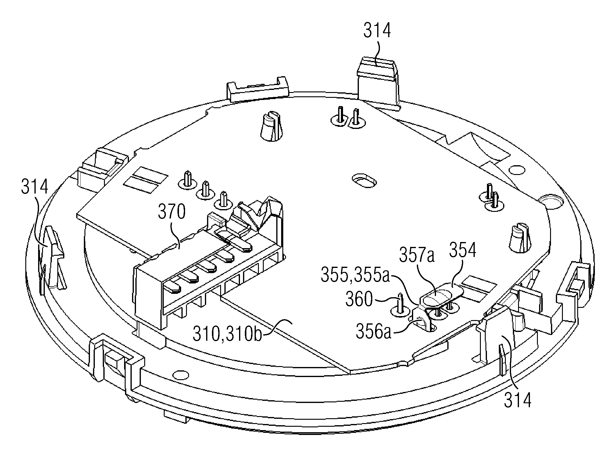
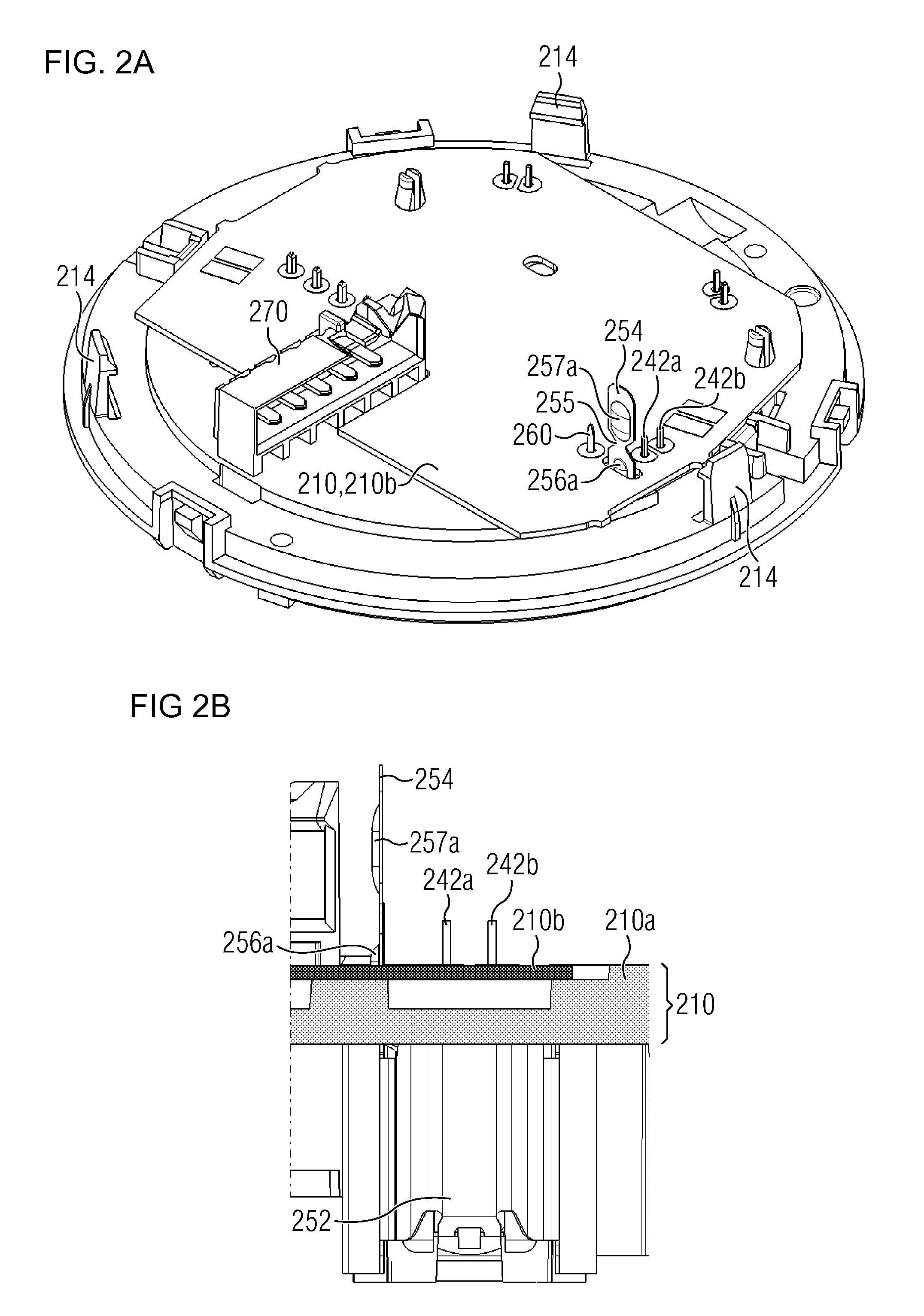
[0054]It should be noted at this point that the reference characters of identical or corresponding components differ from one another only in their first digit.

[0055]It should also be noted that embodiments described in the following merely represent a restricted selection of possible embodiment variants of the invention. In particular, it is possible to combine the features of individual embodiments with each other in a suitable manner so that, for the person skilled in the art, a plurality of different embodiments is to be regarded as obviously disclosed with the embodiment variants explicitly illustrated here.

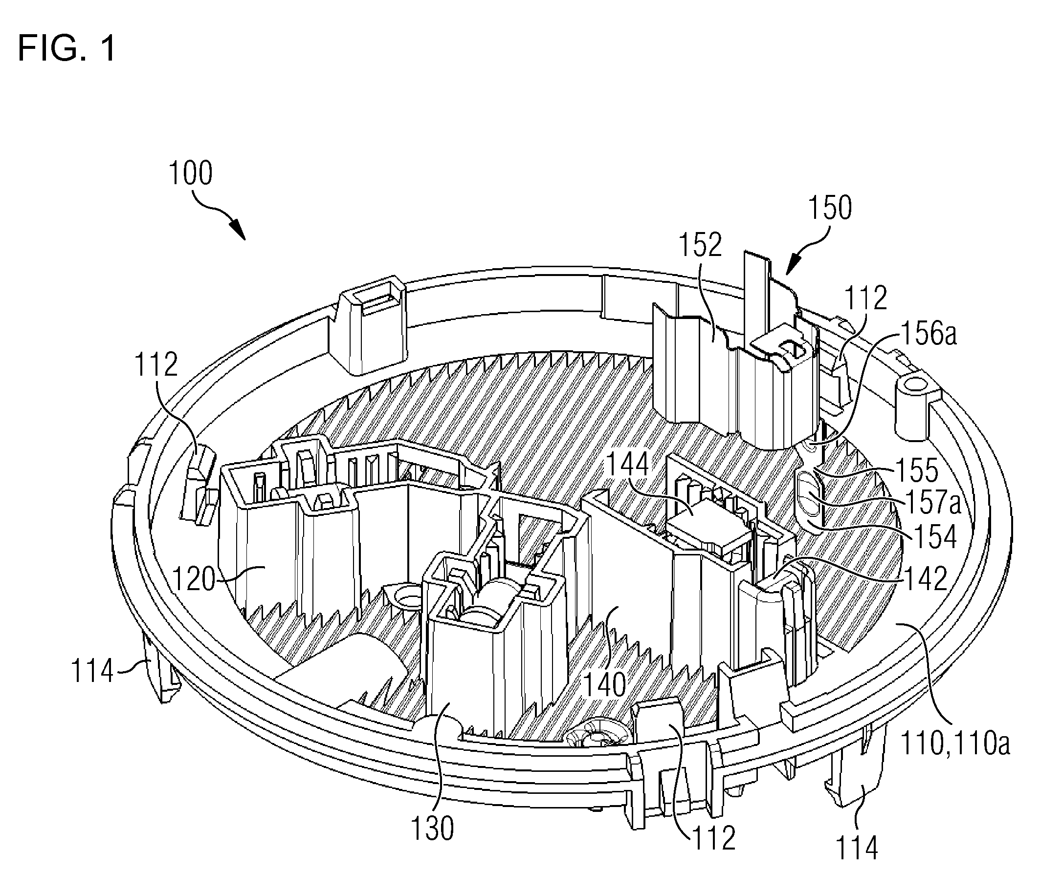
[0056]FIG. 1 shows the installation of a shielding device 150 into a substrate 110 of a smoke alarm 100. The substrate 110 comprises a mechanical support element 110a and a printed circuit board, whereby the printed circuit board is not visible in the perspective view shown in FIG. 1.

[0057]On the mechanical support element 110a are formed snap hooks 112 which are provided fo...


PUM


Abstract

A light receiver device, which is particularly suited for a smoke detector, has a flat substrate, a light receiver mounted on a front side of the substrate, and a shielding device present on at least a back side of the substrate opposite the front side. The shielding device is configured to at least partially shield against electromagnetic interference radiation impinging on the light receiver through the substrate. False alarms are thereby reduced, while the sensitivity of the light receiver is simultaneously increased. The shielding device is formed with a metal strip inserted through the substrate from the front side to the back side, and bent over a recess on the back side provided therefor, so that the light receiver is protected against interference radiation even on the back side. There is also provided an assembly method for producing a light receiver device.

Description

BACKGROUND OF THE INVENTIONField of the Invention[0001]The present invention relates generally to the area of technology of shielding light receivers against electromagnetic interference radiation. The present invention relates specifically to a light receiver device, in particular for an optical smoke alarm, which light receiver device comprises a light receiver and a shielding device that are mounted on a common substrate. The present invention also relates to an assembly method for manufacturing a light receiver device of the aforementioned type.[0002]In order to offer early detection of the unwanted occurrence of a hazardous situation such as for example the start of a fire, danger alarms are frequently used which are fitted at suitable locations in an area being monitored for dangers, for example inside a building. A danger alarm can also be a part of a danger alarm system or a comprehensive building management system which has a plurality of peripheral units in addition to a c...

Claims


Application Information

Patent Timeline
IPC IPC(8): G08B17/10
CPCG08B29/18G08B17/107G08B17/113Y10T29/49826
Inventor RIEDI, URS
Owner SIEMENS SWITZERLAND
Why Eureka
Try Eureka