Electrical contact composites and method for producing electrical contact composites

Active Publication Date: 2018-03-01
SAINT-GOBAIN GLASS FRANCE
View PDF2 Cites 1 Cited by
  • Summary
  • Abstract
  • Description
  • Claims
  • Application Information

AI Technical Summary

Benefits of technology

The present invention provides an electrical contact composite with improved mechanical stability. This is achieved through the use of specific methods and characteristics. In summary, the invention is an electrical contact composite with improved mechanical stability.

Problems solved by technology

It has been demonstrated in practice that such a contact composite is subject to high wear and can break, which may even be accompanied by substrate breakage (e.g., glass breakage).
Since this results in a complete functional failure of the panel heating element, which always requires repair by service personnel, it is desirable to implement the contact composite in as stable a manner as possible.
However, this undesirably increases production costs.

Method used


Image

  • Electrical contact composites and method for producing electrical contact composites
  • Electrical contact composites and method for producing electrical contact composites

Examples


Embodiment Construction

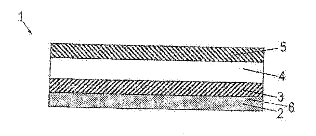
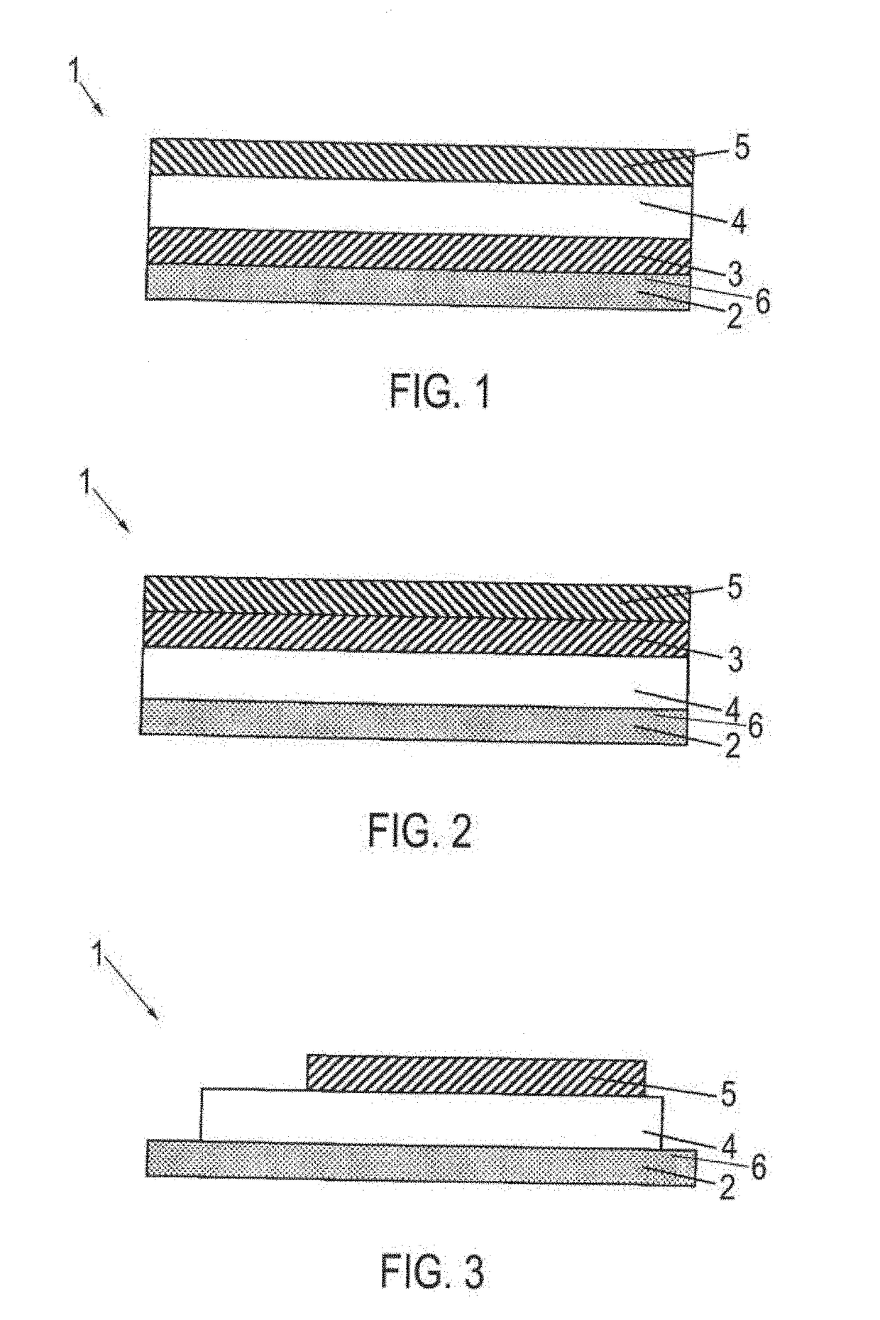
[0036]FIG. 1 illustrates a contact composite referenced as a whole with the reference number 1, which is part of a flat electrical structure (not further shown). The flat electrical structure can, for example, be a panel heating element, in particular a heatable glazing, or a planar antenna. The heatable glazing can be implemented, for example, in the form of a composite pane in which two individual panes are bonded to each other by a thermoplastic adhesive layer. Likewise, the heatable glazing can be a so-called single-pane security glass that comprises only one individual pane.

[0037]The contact composite 1 comprises at least a flat substrate 2 with an electrically conductive coating 6 applied thereon, which is not shown in detail in FIG. 1. As used here, the term “substrate” refers, for example, to a single pane (carrier) of a composite pane or a single pane glass or to the carrier of a planar antenna.

[0038]The substrate 2 is made, for example, of a glass material, such as float g...


PUM

PropertyMeasurementUnit
Thicknessaaaaaaaaaa
Electrical conductivityaaaaaaaaaa
Structureaaaaaaaaaa

Abstract

An electrical contact composite is described. The electrical contact composite has a substrate and an electrically conductive coating applied to the substrate, which coating is connected to an electrode. A metal contact element is connected to the electrode, which contact element is used to connect the conductive coating to a current / voltage source. Furthermore, at least one sprayed layer produced by means of a thermal spraying method, in particular gas dynamic cold spray, and is provided with at least one metal and / or metal alloy, the sprayed layer being arranged between the conductive coating and the contact element. The sprayed layer has a coefficient of thermal expansion that is between the coefficients of thermal expansion of the carrier and of the contact element. The sprayed layer can also be used as the electrode for the conductive coating.

Description

CROSS REFERENCE TO RELATED APPLICATIONS[0001]The present application is a Continuation application Ser. No. 14 / 237,456 filed on Mar. 24, 2014 which in turn claims priority US National Stage of International Patent Application PCT / EP2012 / 064992 filed on Aug. 1, 2012 which, in turn, claims priority to European Patent Application EP 11176894.1 filed on Aug. 9, 2011, all of which are incorporated herein by reference in their entirety.BACKGROUND[0002]The invention is in the technical area of the production of flat electrical structures with a substrate and an electrically conductive coating applied thereon and relates to the electrical contact composite of flat electrical structures as well as methods for producing electrical contact composites.[0003]Flat electrical structures with a substrate of an electrically insulating material and an electrically conductive coating applied thereon are sufficiently known per se. They are frequently used as transparent or opaque panel heating elements...

Claims


Application Information

Patent Timeline
IPC IPC(8): H01R4/58C23C24/04B32B17/10H05B3/84C23C4/06H01R4/04
CPCC23C24/04H01R4/58B32B17/1022B32B17/10174Y10T428/12493H05B3/84H01R4/04C23C4/06H05B2203/016
Inventor RATEICZAK, MITJAREUL, BERNHARD
Owner SAINT-GOBAIN GLASS FRANCE
Why Eureka
Try Eureka