

Display apparatus
a display apparatus and substrate technology, applied in the direction of display means, cooling/ventilation/heating modifications, instruments, etc., to achieve the effect of maintaining heat dissipation performance and thinning the display apparatus
- Summary
- Abstract
- Description
- Claims
- Application Information
AI Technical Summary
Benefits of technology
Problems solved by technology
Method used
Image

Examples
first embodiment
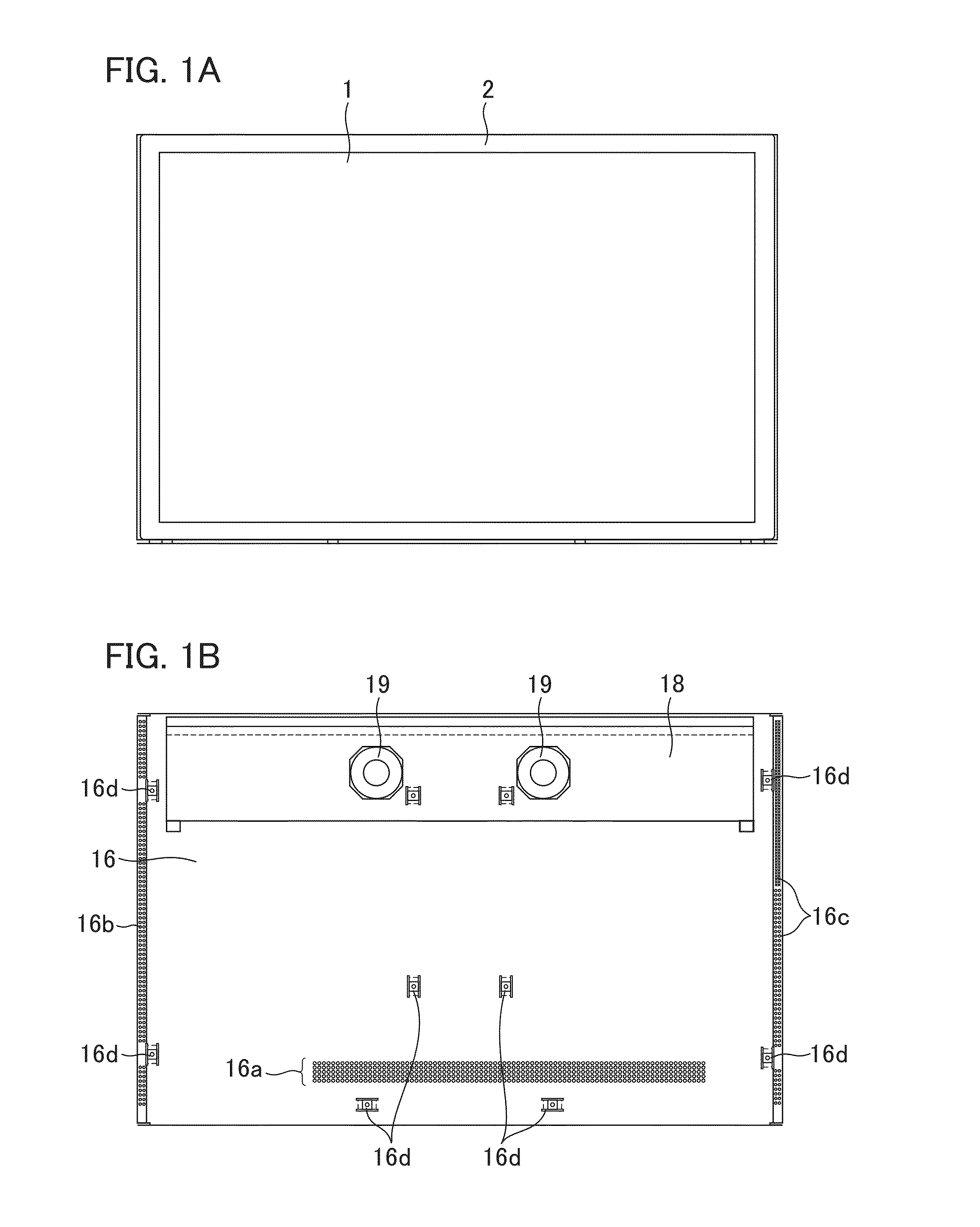
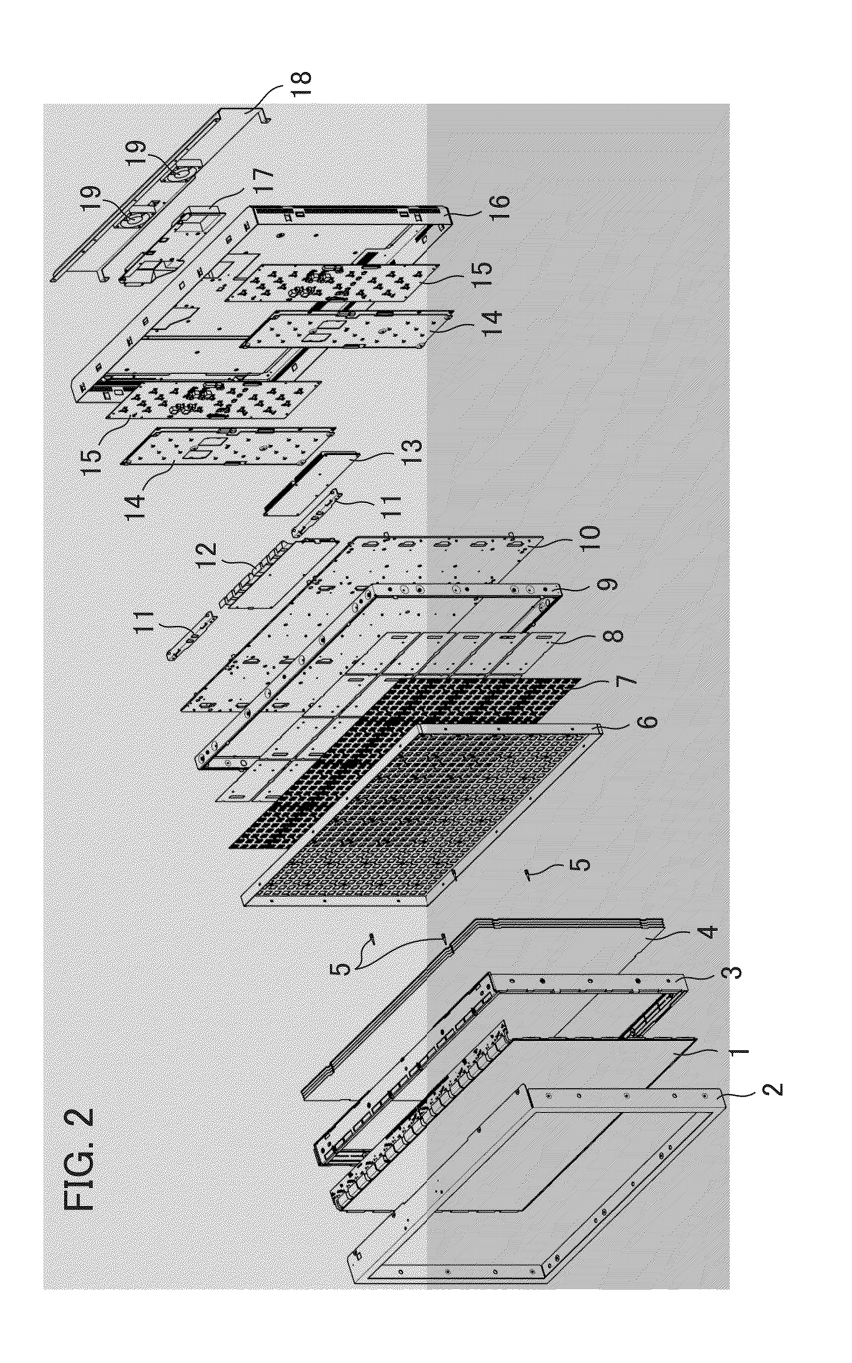
[0023]FIG. 1A is a front view illustrating a display apparatus according to a first embodiment of the present invention and FIG. 1B is a rear view illustrating a display apparatus according to a first embodiment of the present invention. FIG. 2 is an exploded perspective view illustrating the display apparatus according to the first embodiment. In the following, a description will be given of a positional relation of each section by defining the upper face, the lower face, the right side face and the left side face when seen from the front of the display face of the apparatus by a user. An exemplary backlight configuration in which a display unit has a display panel and a light source unit which irradiates the display panel with light is shown.
[0024]As shown in FIG. 1A, the image display apparatus includes a liquid crystal panel 1 as a display panel, and the peripheral edges of the front face of the liquid crystal panel 1 are held by a frame 2 formed of a metal material or the like....
second embodiment
[0038]Next, a description will be given of a second embodiment of the present invention. In the following, components corresponding to or similar to those in the first embodiment are designated by the same reference numerals, and therefore, its explanation will be omitted. A description will be given mainly of the difference from the first embodiment. A description of the embodiments to be described below will be omitted in the same way. FIG. 5 is a rear view illustrating an image display apparatus according to the second embodiment with a chassis removed therefrom.
[0039]In the second embodiment, the shape and arrangement of LED driver substrates are different from those in the first embodiment shown in FIG. 3. A plurality of LED driver substrates 214 are arranged below the display control substrate 12. Two LED driver substrates 214 that are arranged symmetrically to the left and right with respect to the center line Y of a vertical direction of the image display apparatus are conne...
third embodiment
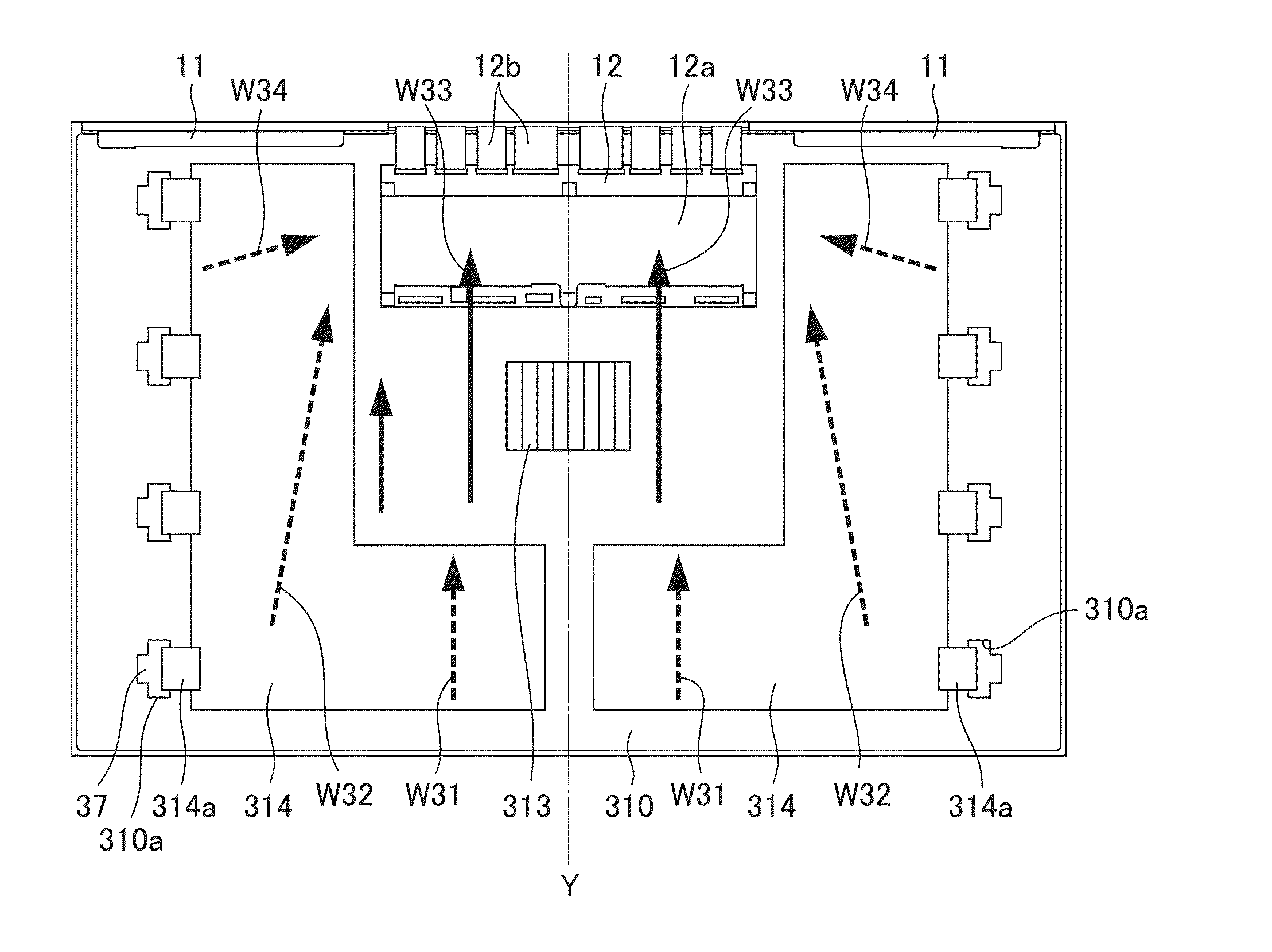
[0042]Next, a description will be given of a third embodiment of the present invention. FIG. 6 is a rear view illustrating an image display apparatus according to the third embodiment with a chassis removed therefrom.
[0043]A plurality of LED driver substrates 314 has an L-shaped plate and is arranged laterally to the right and left sides of the display control substrate 12 and below the display control substrate 12. The LED driver substrates 314 are arranged symmetrically to the left and right with respect to the center line Y of the vertical direction of the image display apparatus. The LED substrates 37 are connected to the LED driver substrate 314 via a plurality of holes 310a formed in an LED heat sink 310 using a plurality of FFCs 314a.
[0044]Air that has drawn from a plurality of vent holes 16a positioned below the chassis 16 shown in FIG. 1B passes between the LED driver substrate 314 and the LED heat sink 310 along the arrows W31 and W32 in FIG. 6 to thereby flow toward the ...
PUM
 Abstract
Description
Claims
Application Information