Apparatus and method for phase equilibrium with in-situ sensing

a technology of in-situ sensing and apparatus, applied in the direction of material heat development, instruments, borehole/well accessories, etc., can solve the problems of requiring a larger sample volume, requiring a relatively large equipment footprint and sample volume, and requiring several hours, days or weeks, so as to achieve the effect of efficient measurement of both the density and viscosity of the sampl

Active Publication Date: 2013-09-19
SCHLUMBERGER TECH CORP
View PDF5 Cites 28 Cited by
  • Summary
  • Abstract
  • Description
  • Claims
  • Application Information

AI Technical Summary

Benefits of technology

[0012]In general, the present invention provides an apparatus and method related to measuring thermodynamic properties of reservoir fluids. The technique utilizes a modular sensor assembly designed to evaluate a sample of a hydrocarbon containing fluid within a cell body. A variety of sensors may be selectively placed into communication with a sample chamber within the cell body to evaluate the sample at potentially high pressures and temperatures. By way of example, the sensors may comprise a single density-viscosity sensor located in-situ to efficiently measure both the density and viscosity of the sample as a function of pressure and temperature. Other sensors, such as an optic sensor and / or a pressure-temperature sensor, may also be positioned to measure parameters of the sample while the sample is retained in the sample chamber.

Problems solved by technology

Mercury has several obvious drawbacks and over the last several years the industry trend generally has been to move away from such designs.
One of the major drawbacks of these larger cells is the requirement of a larger sample volume.
These flow-through type sensors have many drawbacks, including a relatively large equipment footprint and sample volume requirement.
Stratification will occur naturally, but this can take several hours, days, or weeks depending on the fluid system.
In any case, existing devices lack sufficient sensor capabilities or combinations of sensor capabilities to enable sufficient phase behavior and sample validation studies of reservoir fluids.

Method used


Image

  • Apparatus and method for phase equilibrium with in-situ sensing
  • Apparatus and method for phase equilibrium with in-situ sensing
  • Apparatus and method for phase equilibrium with in-situ sensing

Examples


Embodiment Construction

[0044]In the following description, numerous details are set forth to provide an understanding of the present invention. However, it will be understood by those of ordinary skill in the art that the present invention may be practiced without these details and that numerous variations or modifications from the described embodiments may be possible.

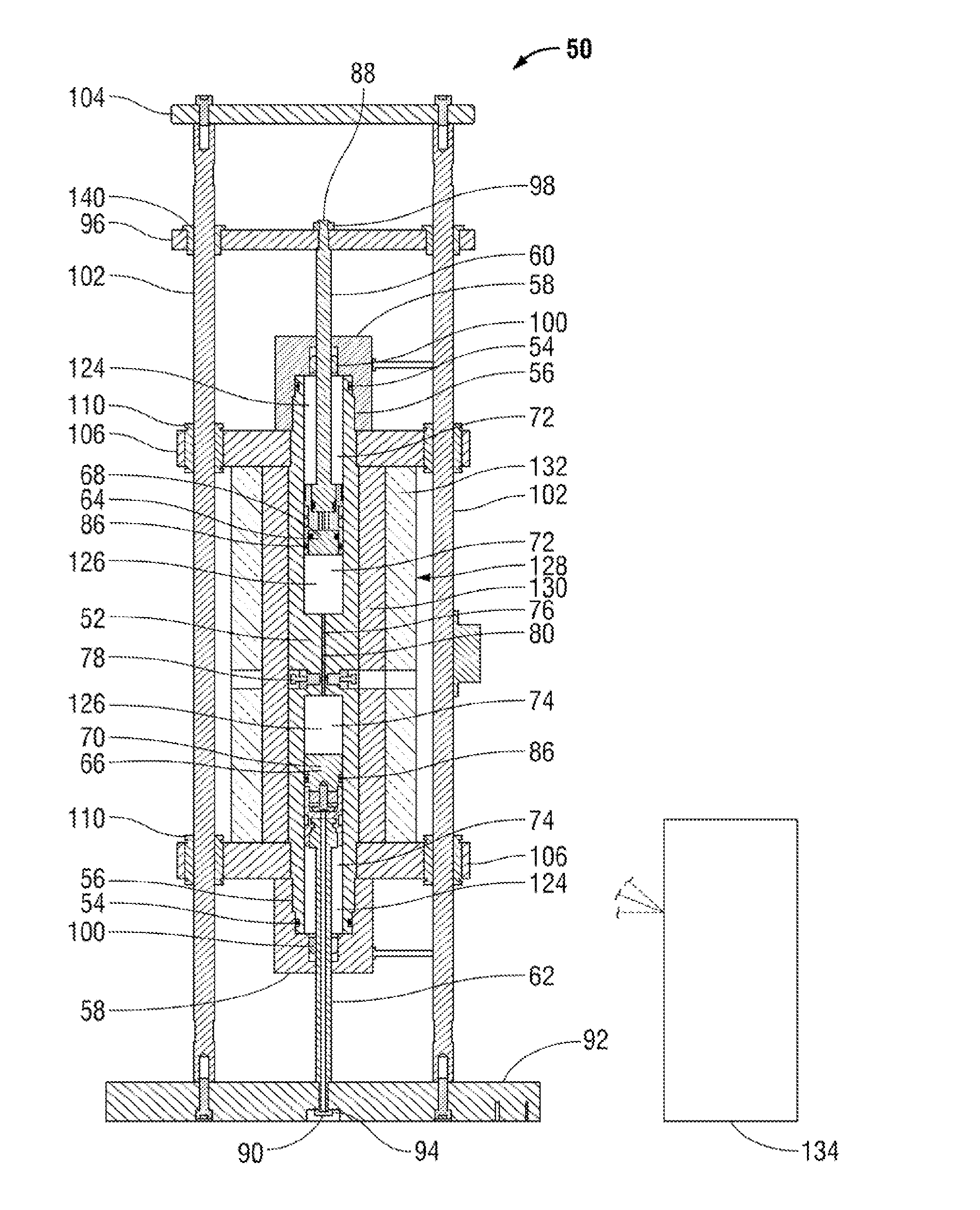
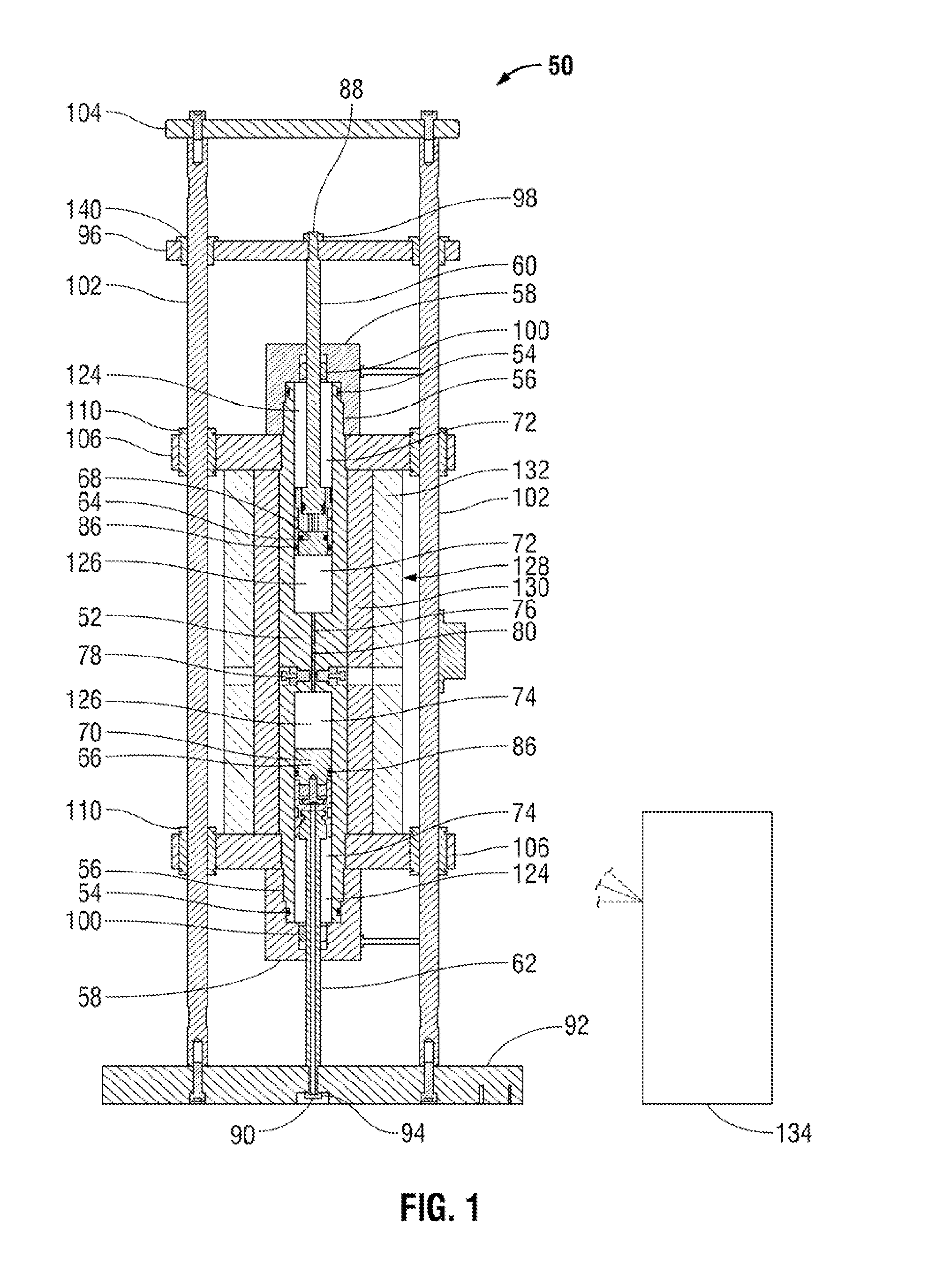
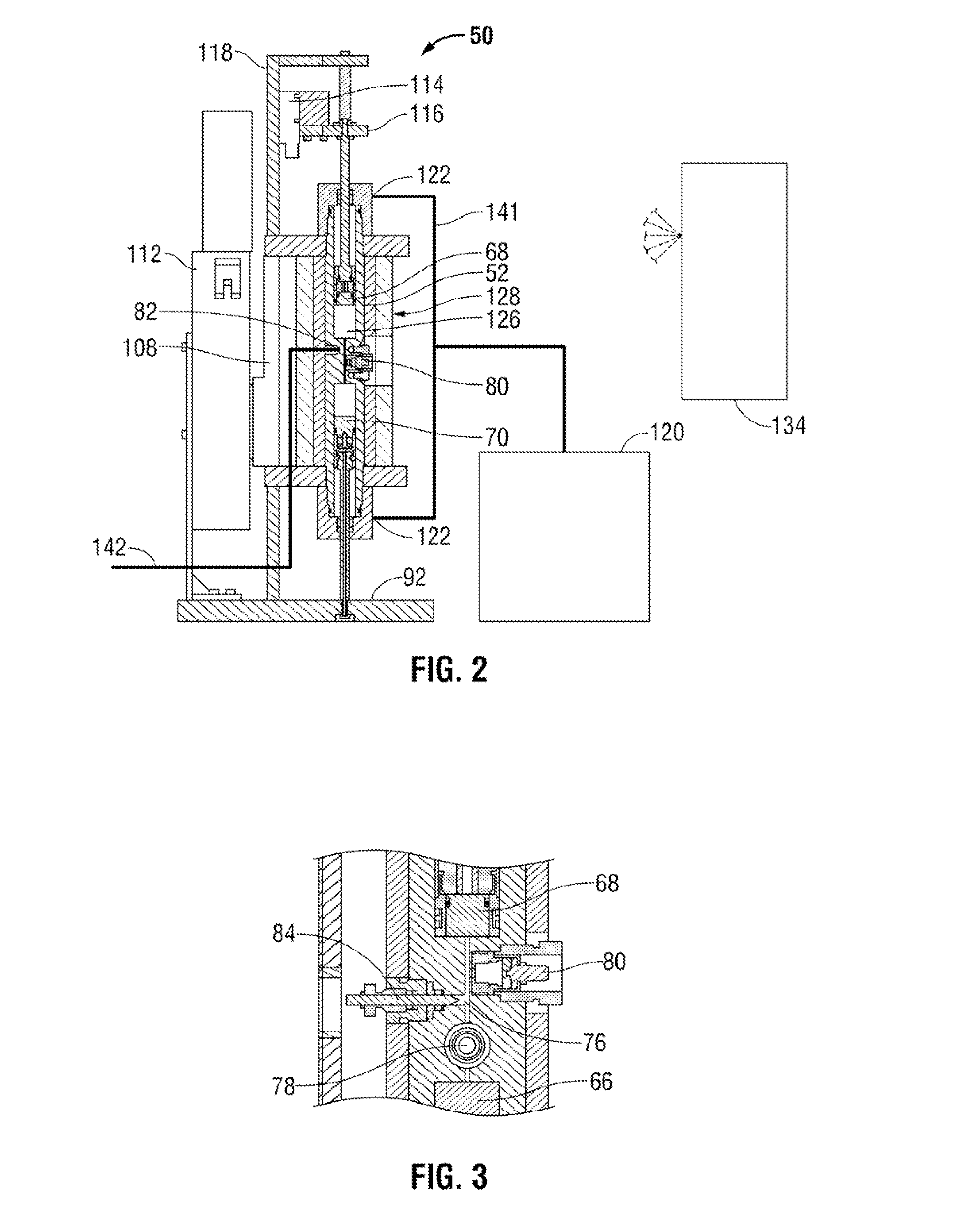
[0045]The present invention relates to a method and system which enhances the overall service quality and data quality with respect to measurement and analysis of reservoir fluid samples. A variety of components are selectively integrated into a modular assembly to simplify the actions involved in measurement and analysis of the reservoir fluid samples. As a result, the reservoir fluid analysis process is more reliable and repeatable during many or all phases of the procedure. The system also is easily portable to wellsites and other desired locations.

[0046]As described herein, the invention relates to an apparatus for measuring thermodynam...


PUM

PropertyMeasurementUnit
temperaturesaaaaaaaaaa
pressuresaaaaaaaaaa
temperatureaaaaaaaaaa

Abstract

A technique facilitates the monitoring of thermodynamic properties of reservoir fluids. The technique utilizes a modular sensor assembly designed to evaluate a sample of a hydrocarbon-containing fluid within a cell body. A variety of sensors may be selectively placed into communication with a sample chamber within the cell body to evaluate the sample at potentially high pressures and temperatures. The sensors may comprise a density-viscosity sensor located in-situ to efficiently measure both the density and viscosity of the sample as a function of pressure and temperature. Other sensors, such as an optic sensor, may also be positioned to measure parameters of the sample while the sample is retained in the sample chamber.

Description

CROSS-REFERENCE TO RELATED APPLICATION[0001]The present application claims priority from U.S. Provisional Application 61 / 377,167, filed Aug. 26, 2010, which is incorporated herein by reference.BACKGROUND OF THE INVENTION[0002]In many oilfield applications, reservoir fluid samples are collected and thermodynamic studies and / or other studies are performed to obtain desired information on a subterranean reservoir. The thermodynamic studies involve measuring thermodynamic properties of reservoir fluids for phase behavior analysis and / or sample validation.[0003]Phase behavior of reservoir fluids can be characterized using a plurality of apparatus types. Generally these devices are in the form of pressure retaining vessels capable of withstanding high temperatures and pressures. The pressure retaining vessels or cells use either mercury or pistons (in the case of mercury-free cells) to impart pressure onto the fluid sample via some type of displacement pump or mechanical drive. In mercury...

Claims


Application Information

Patent Timeline
Patent Type & Authority Applications(United States)
IPC IPC(8): G01N25/00
CPCG01N9/002G01N9/34G01N25/00G01N11/16G01N33/2823G01N11/04E21B49/00
Inventor SINGH, ANILSCHMIDT, KURTABBOTT, BRIANSCHROEDER, ROBERT J.DONZLER, ERIC PAUL
Owner SCHLUMBERGER TECH CORP
Why Eureka
Try Eureka