Bearing housing shroud
- Summary
- Abstract
- Description
- Claims
- Application Information
AI Technical Summary
Benefits of technology
Problems solved by technology
Method used
Image

Examples
Embodiment Construction
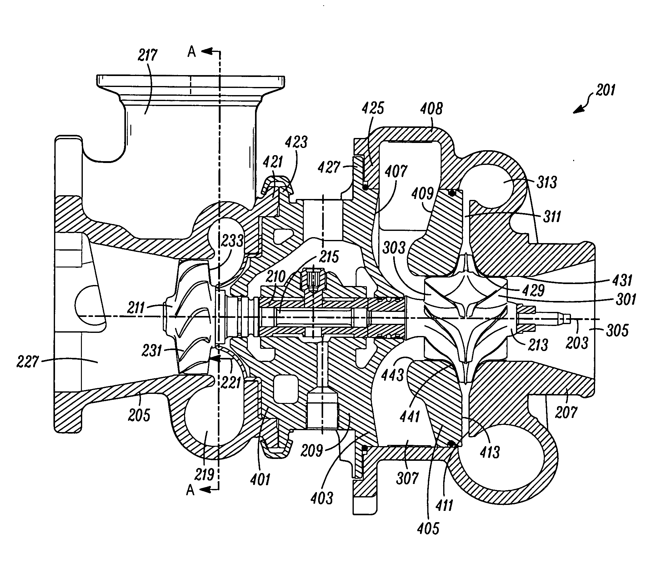
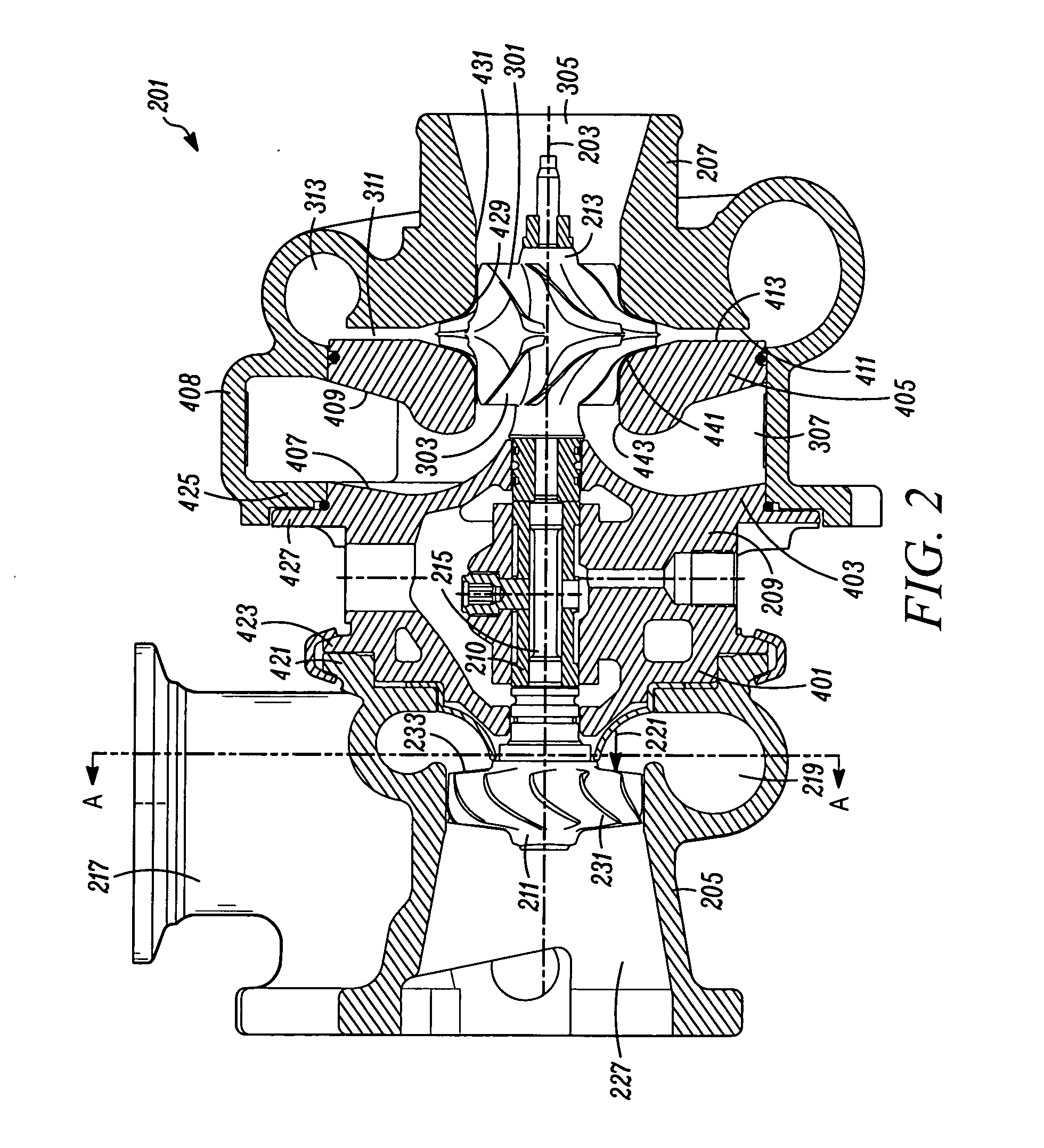
[0025]The invention summarized above and defined by the enumerated claims may be better understood by referring to the following detailed description, which should be read with the accompanying drawings. This detailed description of particular preferred embodiments of the invention, set out below to enable one to build and use particular implementations of the invention, is not intended to limit the enumerated claims, but rather, it is intended to provide particular examples of them.
[0026]Typical embodiments of the present invention reside in a motor vehicle equipped with a gasoline powered internal combustion engine (“ICE”) and a turbocharger. The turbocharger is equipped with a unique combination of features that may, in various embodiments, provide the aerodynamic benefits of a zero reaction turbine with the geometric benefits of a fifty percent reaction turbine, and / or provide significantly improved system efficiencies by combining less efficient components in a manner that redu...
PUM
 Abstract
Description
Claims
Application Information