Composite Protective Element for a Thermally Insulated Pipe

a protective element and thermal insulation technology, applied in the direction of pipe elements, rigid pipes, couplings, etc., can solve the problems of poor sealing between sections, leakage of pipes and their connections, loss of seal at the valve system,

Inactive Publication Date: 2013-09-26
DAHER AEROSPACE
View PDF5 Cites 5 Cited by
  • Summary
  • Abstract
  • Description
  • Claims
  • Application Information

AI Technical Summary

Benefits of technology

[0016]The invention is aimed at providing a protecting element for the thermal insulation of a piping, so as to form a shell of thermal insulation. This protective element providing an additional support function for a technical equipment and leading to a quick and easy installation of this equipment while ensuring its suitable positioning, said installation remaining reliable over time.

Problems solved by technology

The risk of leaking pipes and their connections are, for example related to a crack in the pipe, poor seal between sections, or loss of seal at the valve systems.
Also, leaks can lead to a loss of function by the end system to be supplied (defrosting, air conditioning etc.)
These detection devices can only be put in place after the piping has been installed.
Because of the intertwining of pipes in a small space, the work of putting in place and fastening a number of rings is not practical and remains fastidious, the more so since it is subsequently necessary to correctly position the cable with the sensors and the sensors opposite the aeration holes.
Besides, an incorrectly fastened ring can lead to cable movement and thus a shift in the position of one or more sensors, which destroys the chance of efficient or even effective detection.

Method used


Image

  • Composite Protective Element for a Thermally Insulated Pipe
  • Composite Protective Element for a Thermally Insulated Pipe
  • Composite Protective Element for a Thermally Insulated Pipe

Examples


Embodiment Construction

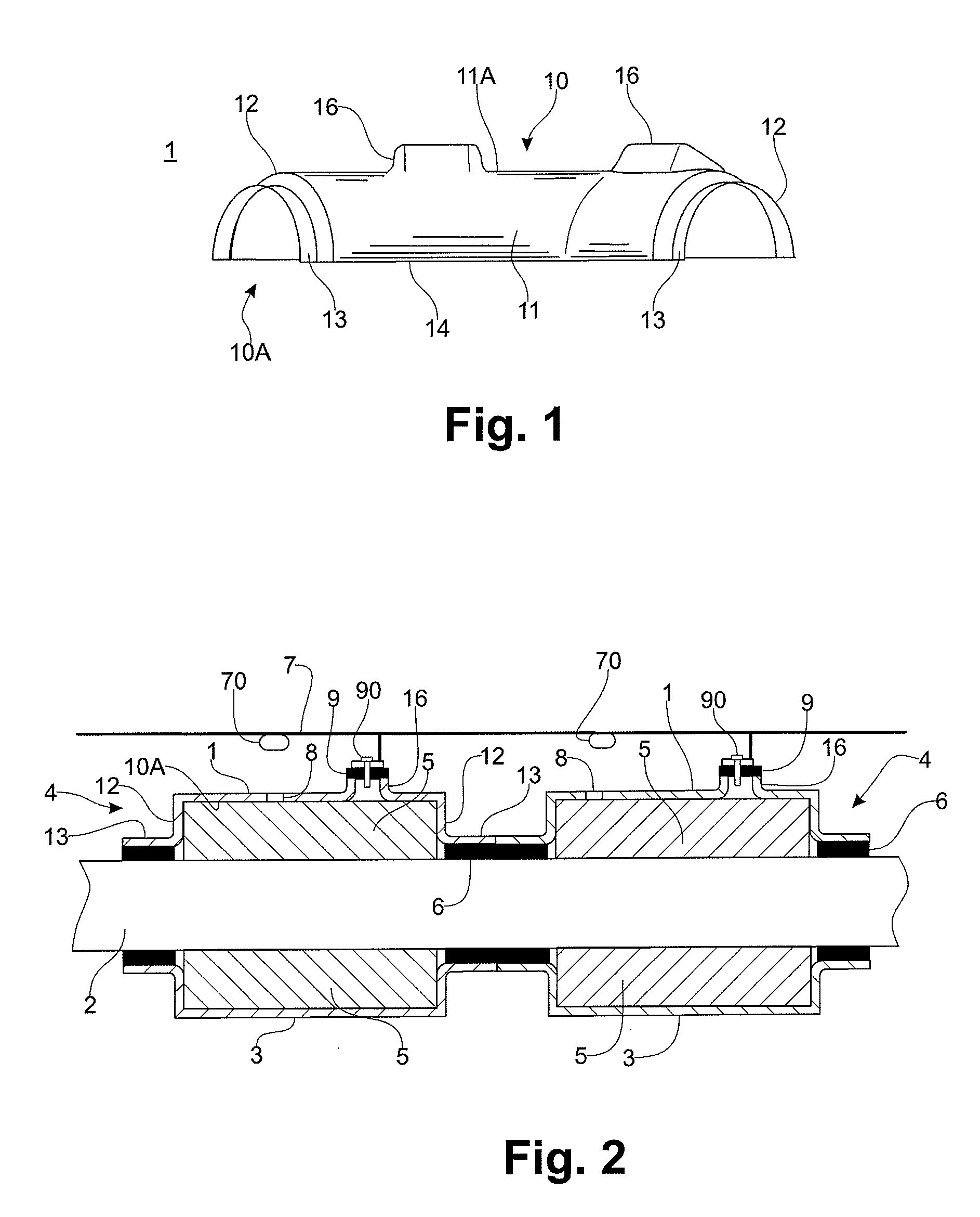
[0039]FIG. 1 illustrates a protection element 1 according to the invention for the thermal insulation of pipes.

[0040]This protection element, with an open concavity 10A, forms a half shell. It is made of a composite material comprising a plastic binder such as an epoxy resin reinforced by fibers with thermal insulation properties such as glass fibers.

[0041]Such a half shell is designed to cover pipes by being assembled opposite a half shell with similar mechanical and insulating properties and generally an equivalent shape, to form a protective shell.

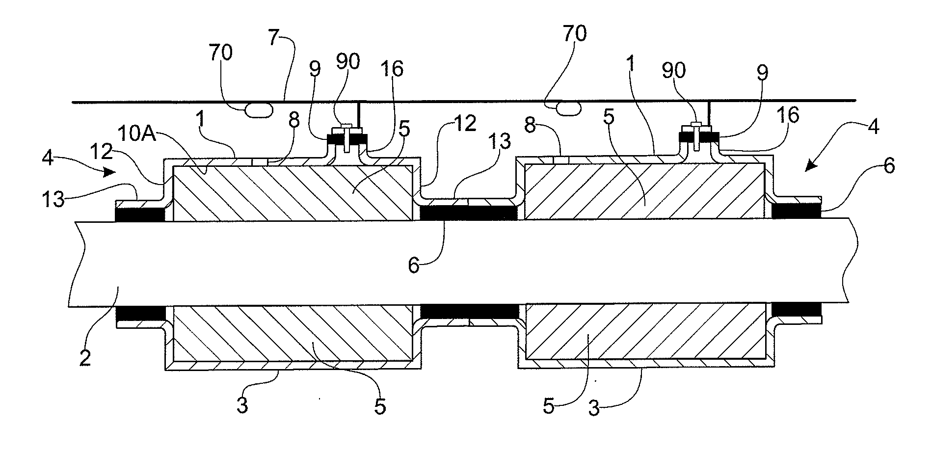
[0042]FIG. 2 represents a sectional view of a pipe 2 sandwiched between one half shell 1 of the invention and the complementary half shell 3, together making up a protective shell 4 around the pipe. Such a shell is for instance used for the thermal protection of the pipes used in aircraft, which convey air at a high temperature (up to 540° C.). The pipes are wrapped in thermal insulation 5 such as foam or insulating wool and covered by ...


PUM


Abstract

A thermally insulating protection element for piping, including a hollow body with an open concavity and having a wall. The wall includes at least one rigid positioning and/or support platform designed to accommodate the fastening of technical equipment to be associated with the protection element. The element is designed to not only insulate piping, but also to constitute a direct device for supporting and fastening technical equipment such as a sensing line.

Description

[0001]This application is a continuation in part of co-pending U.S. application Ser. No. 12 / 659,583 which is incorporated herein in its entirety by reference.FIELD OF THE INVENTION[0002]The invention relates to a protection element for the thermal insulation of piping, the element being also designed to act as a supporting device for a technical equipment that has to be routed along the piping. In particular, the technical equipment ideally follows the piping in order to detect any leaks from the piping.[0003]The invention has been described more particularly in the context of the use of such protection elements in the field of aeronautics, for piping particularly carrying air at a high temperature and / or under high pressure. However, the invention applies to all areas involving protection elements or shells for piping.[0004]In aircraft, dozens of meters of piping are arranged to collect air at high temperatures (260 to 540° C.) or under pressure (5 to 15 bar) from certain areas, su...

Claims


Application Information

Patent Timeline
Patent Type & Authority Applications(United States)
IPC IPC(8): F16L59/10
CPCF16L59/135F16L59/11F16L59/10F16L2201/30
Inventor BOURLART, REMI
Owner DAHER AEROSPACE
Why Eureka
Try Eureka