Method of and apparatus for casting metal slab

a technology of metal slabs and nozzles, applied in the field of methods and nozzles for casting metal, can solve the problems of higher equipment and production costs, and achieve the effect of reducing the effective length of the caster cavity and pronounced effect of depressing the nozzles

Active Publication Date: 2013-09-26
NOVELIS INC
View PDF4 Cites 1 Cited by
  • Summary
  • Abstract
  • Description
  • Claims
  • Application Information

AI Technical Summary

Benefits of technology

[0048]Generally, it was observed that installing the depressed nozzles (offset by 1 mm) near the center of the caster increased the gap between the two casting belts by about 0.4 mm in the area with depressed nozzles, with the belt returning to its normal elevation after passing the area with depressed nozzles.
[0049]At the exit end of the caster, the effect of depressing nozzles was more pronounced. At the front edge of the depressed region, the gap between casting belts was increased by the same 0.4-0.5 mm. However, as the last rows of nozzles are positioned immediately before the ‘break’ in the belt path (where the belts normally diverge significantly), the change in the gap between belts was more pronounced in the downstream section of where these nozzles were depressed. The general effect was to decrease the effective length of the caster cavity as though the break in the caster belt path had been moved forward.
[0050]The effect on cavity size of depressing nozzles at the exit of the top carriage was the same as that of depressing nozzles at the exit of the bottom carriage.

Problems solved by technology

The need for slow rates of metal throughput and / or long casting cavities results in higher equipment and production costs than would be the case if rates could be increased and / or casting cavities shortened.

Method used


Image

  • Method of and apparatus for casting metal slab
  • Method of and apparatus for casting metal slab
  • Method of and apparatus for casting metal slab

Examples


example 1

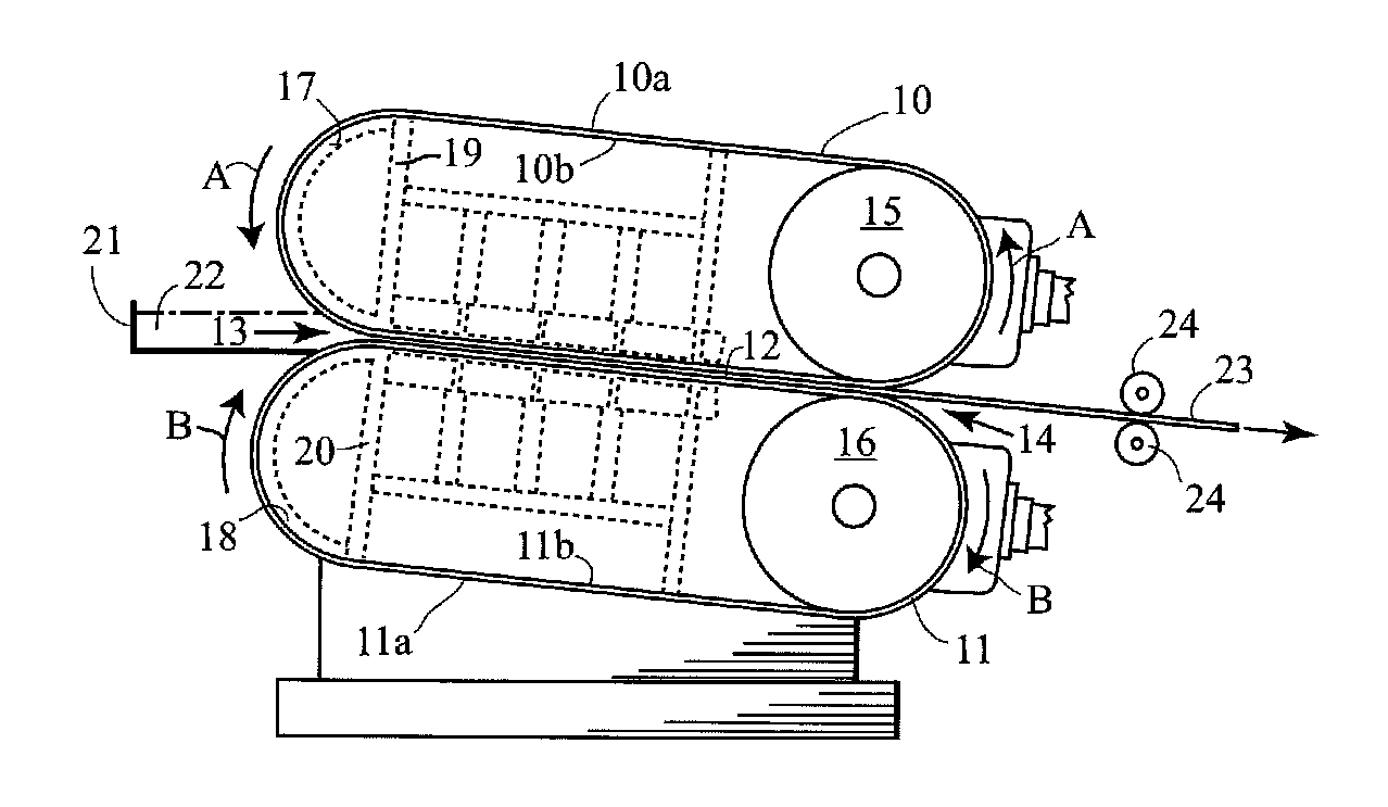
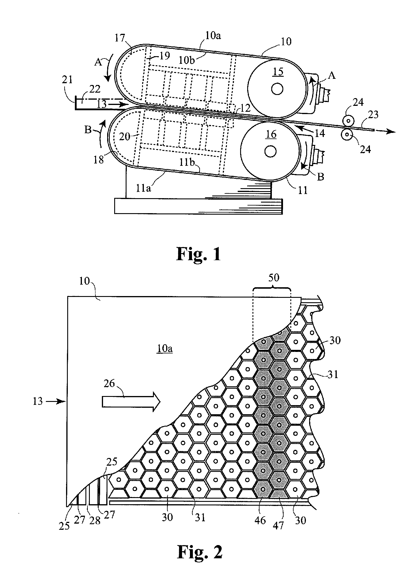
[0041]Experiments were carried out on a laboratory scale twin-belt caster (referred to as “TB2”). The caster had a design generally as shown in FIGS. 1 and 2, and had a casting cavity with a length similar to that of commercial-scale, twin-belt casters; however, the width of the casting belts was smaller than that of commercial casters. The caster was provided with nozzles of special design that allowed all of the cooling nozzles to be adjusted to change their offset spacing from the casting cavity so that the effects of increasing the offset in different regions or for different region sizes could be assessed. The exit temperature of the slab was measured using five contact thermocouples spaced across the bottom of the emerging slab near the outlet of the casting cavity. Heat flux in the caster was monitored using an array of cooling water thermocouples.

[0042]An experiment was conducted with nozzles offset by 1 mm in a central region of the caster, i.e. the second and third row of ...

example 2

[0051]The results described in Example 1 were achieved by modulating the heat flux in part of the caster by mechanically adjusting the nozzle elevations in that region to remove the belt from contact with the slab being cast. However, there are other means of achieving the same or similar results without resorting to mechanical means, as illustrated in this prophetic Example.

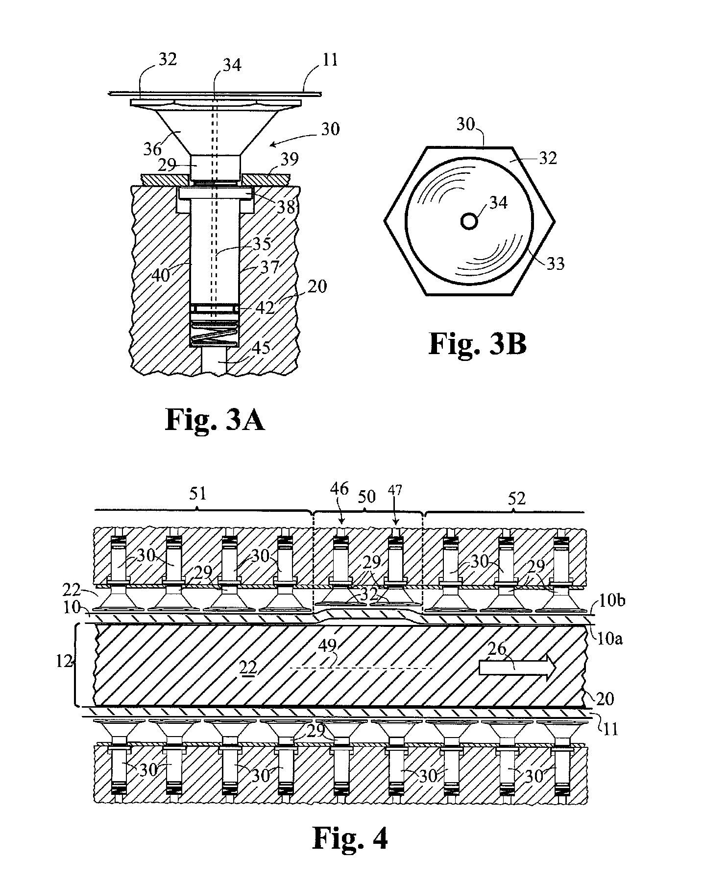
[0052]The caster described above includes a plurality of cooling nozzles beneath the casting belts which supply high pressure water to cool and position the casting belts. The application of the cooling water, its supply pressure and distribution and the internal pressure maintained within the casting machine are all process parameters which determine the velocity of the cooling water across the inner face of each casting belt and hence the belt elevation and the heat extraction rate. These parameters are conventionally controlled for the whole casting machine as it was not considered to be economically feasible...


PUM

PropertyMeasurementUnit
movementaaaaaaaaaa
lengthaaaaaaaaaa
lengthaaaaaaaaaa

Abstract

Embodiments of the invention relate to a method and apparatus for continuously casting a metal slab. The method involves continuously introducing molten metal into an inlet of a casting cavity defined between advancing casting surfaces, cooling the metal in the cavity to form a metal slab, and discharging the slab from the cavity through an outlet. The casting surfaces have an ability to remove heat from the metal but this ability is reduced, thus reducing heat flux, for at least one of the casting surfaces in a region of the cavity spaced from both the inlet and the outlet and extending transversely to the casting direction. This reduced ability to remove heat is relative to such ability of the casting surface in immediately adjacent upstream and downstream regions of the cavity. The apparatus may be a twin belt caster or other form of continuous caster modified to perform the method.

Description

CROSS REFERENCE TO RELATED APPLICATION[0001]This application claims the priority right of prior co-pending provisional patent application No. 61 / 614,118 filed Mar. 22, 2012, by applicants named herein. The entire contents of application Ser. No. 61 / 614,118 are specifically incorporated herein by this reference.BACKGROUND OF THE INVENTION[0002]1. Field of the Invention[0003]This invention relates to a method of and apparatus for casting metal to form metal slabs. More particularly, the invention relates to continuous casting methods and apparatus in which the metal is cast in a casting cavity formed between spaced confronting casting surfaces that are advanced in a casting direction between an inlet for and an outlet from the casting cavity.[0004]2. Background Art[0005]Elongated relatively thin metal slabs (sometimes also referred to as cast strips or bands) may be produced by continuous casting techniques in equipment such as twin-belt casters, rotating block casters, twin-roll cast...

Claims


Application Information

Patent Timeline
Patent Type & Authority Applications(United States)
IPC IPC(8): B22D11/06
CPCB22D11/0605B22D11/0677B22D11/068
Inventor GATENBY, KEVIN MICHAELLUCE, EDWIN STANLEY
Owner NOVELIS INC
Why Eureka
Try Eureka