
Statistical analyzing method and statistical quality indicator for reliability improvement of a capacitive touch device

a capacitive touch and statistical analysis technology, applied in the direction of instruments, computing, electric digital data processing, etc., to achieve the effect of improving the sensing quality of the capacitive touch devi

Inactive Publication Date: 2013-09-26
ELAN MICROELECTRONICS CORPORATION
View PDF4 Cites 12 Cited by
  • Summary
  • Abstract
  • Description
  • Claims
  • Application Information

AI Technical Summary

Benefits of technology

The present invention aims to provide a sensing apparatus and method for better sensing quality in capacitive touch devices. This means that the invention improves how sensitive and accurate the touch devices are in detecting touch input.

Problems solved by technology

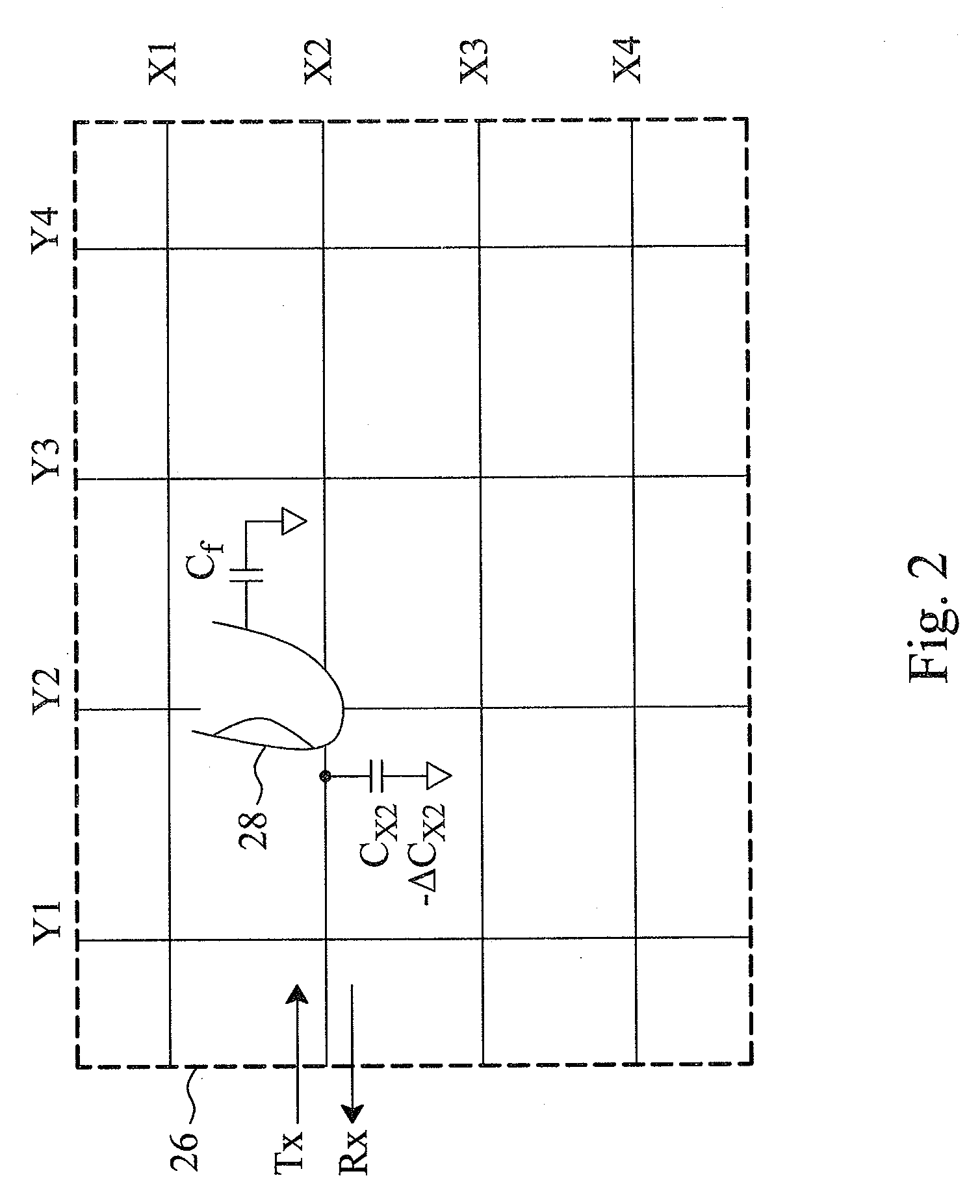
In the course of sensing a capacitive touch sensor for capacitance variation, external noise and capacitive coupling between sensor electrodes can affect the sensed value, making a non-contact point be mistaken for a touch point, or leading to abnormal sensed values generated at a non-contact point that feedback incorrect coordinates and in turn causing mis-operation.

Method used


Image

  • Statistical analyzing method and statistical quality indicator for reliability improvement of a capacitive touch device
  • Statistical analyzing method and statistical quality indicator for reliability improvement of a capacitive touch device
  • Statistical analyzing method and statistical quality indicator for reliability improvement of a capacitive touch device

Examples


first embodiment

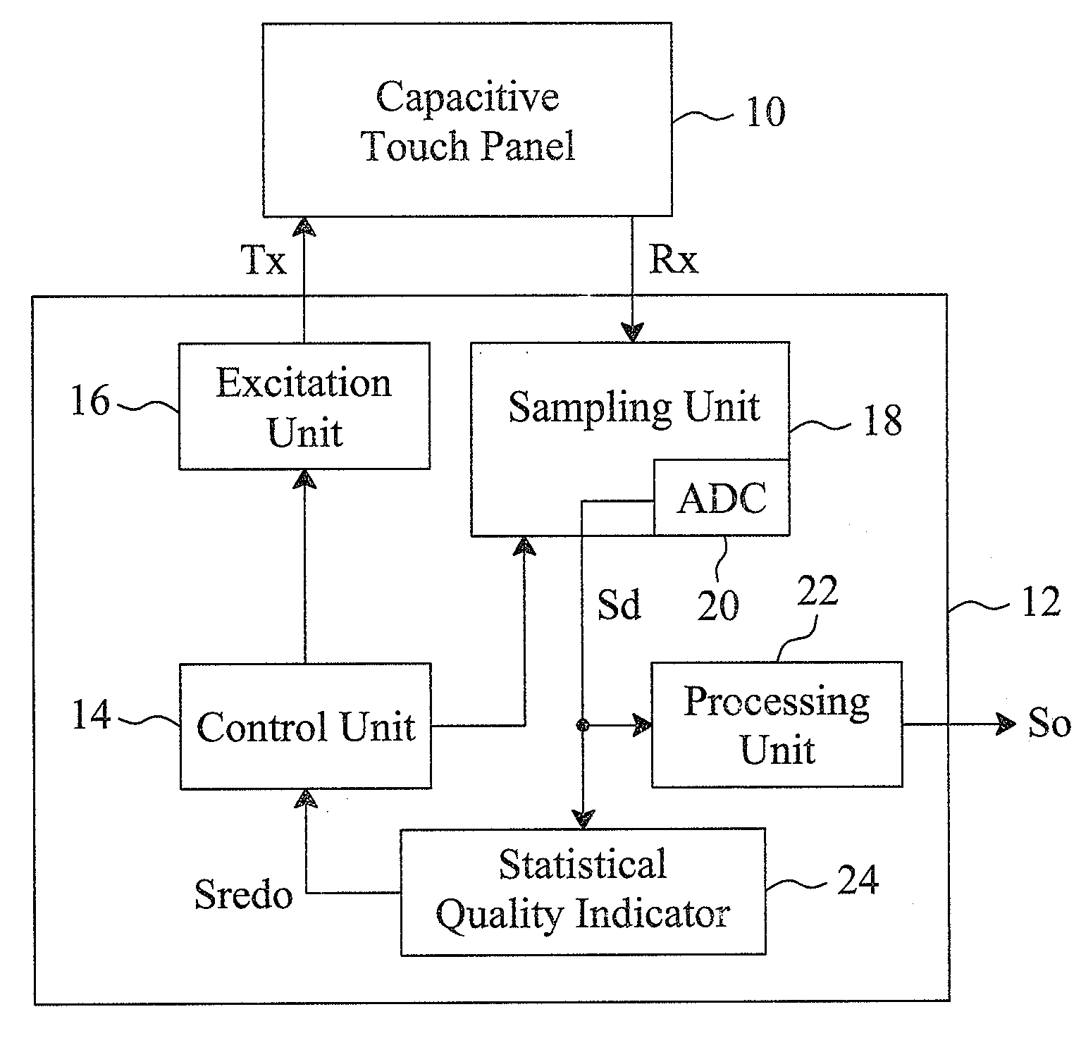
[0020]FIGS. 5 and 6 show a sensing method according to the present invention. The statistical quality indicator 24 shown in FIG. 1 has a defined reasonable range. For example, it has an upper boundary and a lower boundary set as 40 and 25, respectively. The control unit 14 controls the excitation unit 16 and the sampling unit 18 to continuously sense the capacitive touch sensor 26 to generate sensed values Sd. The sensing cycle Tsen is determined based on the sensing frequency. The statistical quality indicator 24 counts the number N of the sensed values Sd that are either larger than the upper boundary 40 (Sd>40) or smaller than the lower boundary 25 (Sd40 and the lower boundary 25. If the defined threshold is 3, then the statistical quality indicator 24 will identify the sensed values Sd in this statistic cycle Tsta as qualified, and the average

30.3(=31+32+29+30+28+326)

will be adopted. On the other hand, as shown in FIG. 6, the six sensed values Sd are 51, 45, 41, 35, 30 and 23, f...

second embodiment

[0021]FIGS. 7 and 8 show a sensing method according to the present invention, by which the statistical quality indicator 24 shown in FIG. 1 calculates the standard deviation σ(Sd) of the sensed values Sd in a statistic cycle Tsta, and compares the standard deviation σ(Sd) to a defined threshold to evaluate the sensing quality. For example, as shown in FIG. 7, the standard deviation σ(Sd) obtained from the six sensed values Sd (31, 32, 29, 30, 28, 32) is 1.49, and as shown in FIG. 8, the standard deviation σ(Sd) obtained from the six sensed values Sd (51, 45, 41, 35, 30, 23) is 9.3. If the defined threshold is 5, then the statistical quality indicator 24 will identify the sensed values Sd shown in FIG. 7 as qualified, and the average 30.3 is adopted; while the statistical quality indicator 24 will identify the sensed values Sd shown in FIG. 8 as not qualified, and trigger a redo signal Sredo to signal the control unit 14 to discard these unqualified sensed values Sd and re-sense the ...


PUM


Abstract

For a capacitive touch device having a capacitive touch sensor to be sensed to generate sensed values, a sensing apparatus and method statistically analyze the sensed values generated in a certain time period to evaluate the sensing quality thereof, discard the poor reliable sensed values, and re-sense the capacitive touch sensor to generate new sensed values, by which the resultant output signal will have improved reliability.

Description

FIELD OF THE INVENTION[0001]The present invention is related generally to a capacitive touch device and, more particularly, to a sensing apparatus and method for a capacitive touch device.BACKGROUND OF THE INVENTION[0002]A capacitive touch device detects a touch point by sensing the capacitance variation from its capacitive touch sensor, and thus its performance highly depends on the accuracy of the sensed capacitance. In the course of sensing a capacitive touch sensor for capacitance variation, external noise and capacitive coupling between sensor electrodes can affect the sensed value, making a non-contact point be mistaken for a touch point, or leading to abnormal sensed values generated at a non-contact point that feedback incorrect coordinates and in turn causing mis-operation.[0003]Therefore, it is desired a reliability improved sensing apparatus and method for a capacitive touch device.SUMMARY OF THE INVENTION[0004]An objective of the present invention is to provide a sensing...

Claims


Application Information

Patent Timeline
Patent Type & Authority Applications(United States)
IPC IPC(8): G06F3/044
CPCG06F3/0418G06F3/044G06F3/0446
Inventor LIN, CHIA-HSINGKUO, PO-HAOTAO, YI-HSIN
Owner ELAN MICROELECTRONICS CORPORATION
Learn More