Apparatus for quantifying unknown stress and residual stress of a material and method thereof

Active Publication Date: 2013-09-26
NATIONAL TSING HUA UNIVERSITY
View PDF7 Cites 13 Cited by
  • Summary
  • Abstract
  • Description
  • Claims
  • Application Information

AI Technical Summary

Benefits of technology

[0010]To accomplish the objective of the present invention, it is noted that the apparatus of the present invention is able to quantify the unknown stress an

Problems solved by technology

The technology for manufacturing displays has been advanced with an unimaginable speed.
However, during the race between technology advancement and consumers' pursuit of higher visual satisfaction, a major problem, MURA, pixel defects or wide-area pixel defects (also known as Mura defects), surfaces itself and bothers the manufacturers a great deal.
As introduced, the quantifying method for measuring material stress has to use different measurement systems to acquire stress-optic coefficient and wavelength, which will lead to accumulation of errors from different systems and is not appropriate for quantifying material stress which requires precise measurement.
In addition, those required stress-optic coefficient and wavelength may not be independent from each other such that when the material stress value is low, i.e., unknown stress and/or residual stress, the final calculation of the stress will not be correct and is not appropriate for measuring material stress.
In addition, the conventional photoelasticity often uses full-field image acquisition

Method used


Image

  • Apparatus for quantifying unknown stress and residual stress of a material and method thereof
  • Apparatus for quantifying unknown stress and residual stress of a material and method thereof
  • Apparatus for quantifying unknown stress and residual stress of a material and method thereof

Examples


first embodiment

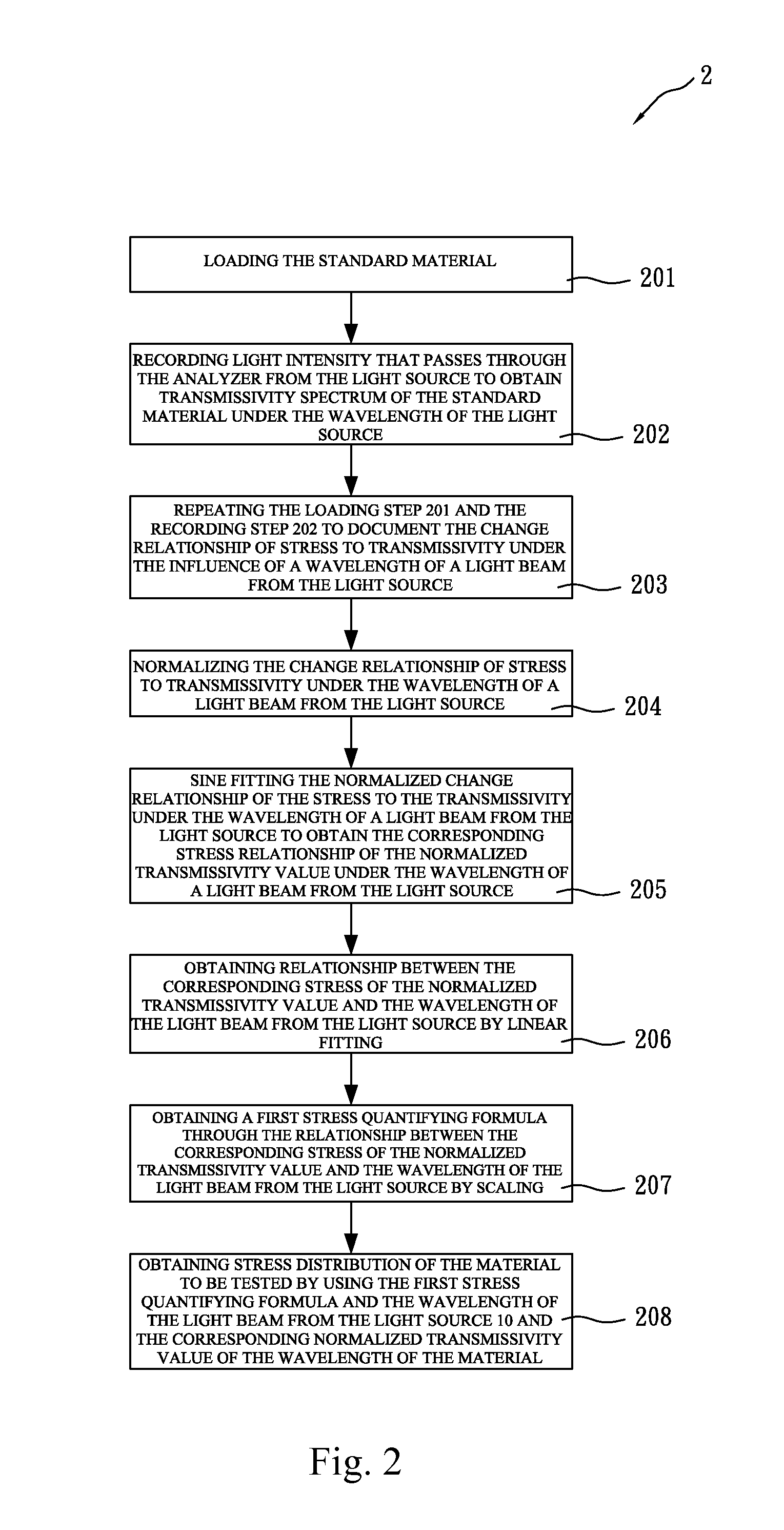
[0077]With reference to FIGS. 1 and 3, if the transmissivity of the material is unknown, then, the method in the present invention further has a step 209. First of all, the material to be tested is used to replace the standard material 13. The spectrometer 17 is implemented to document the light beam intensity passing through the analyzer 15. Thus the transmissivity spectrum of the material to be tested under the wavelength of the light source 10 is obtained. Consequently, the normalized transmissivity of the material to be tested is obtained. In a preferred embodiment of the present invention, the step 209 is carried out immediately after step 207.

embodiment 3

[0078]With reference to FIGS. 1 and 4, the method in the second preferred embodiment 3 of the present invention includes the steps of:

[0079]Step 301: loading a standard material 13; Step 302: recording light intensity that passes through the analyzer 15 from the light source to obtain transmissivity spectrum of the standard material 13 under the wavelength of the light source 10;

[0080]Step 303: repeating the loading step 301 and the recording step 302 to document the change relationship of stress to transmissivity under the influence of a wavelength of a light beam from the light source 10;

[0081]Step 304: normalizing the change relationship of stress to transmissivity under the influence of a wavelength of a light beam from the light source 10;

[0082]Step 305: obtaining relationship between the variation of theappearing wavelength of the normalized transmissivity spectrum and the variation of the stress;

[0083]Step 306: choosing a known stress and the appearing wavelength of the norma...

second embodiment

[0099]With reference to FIGS. 1, 5 and 10, the method of the present invention is shown:

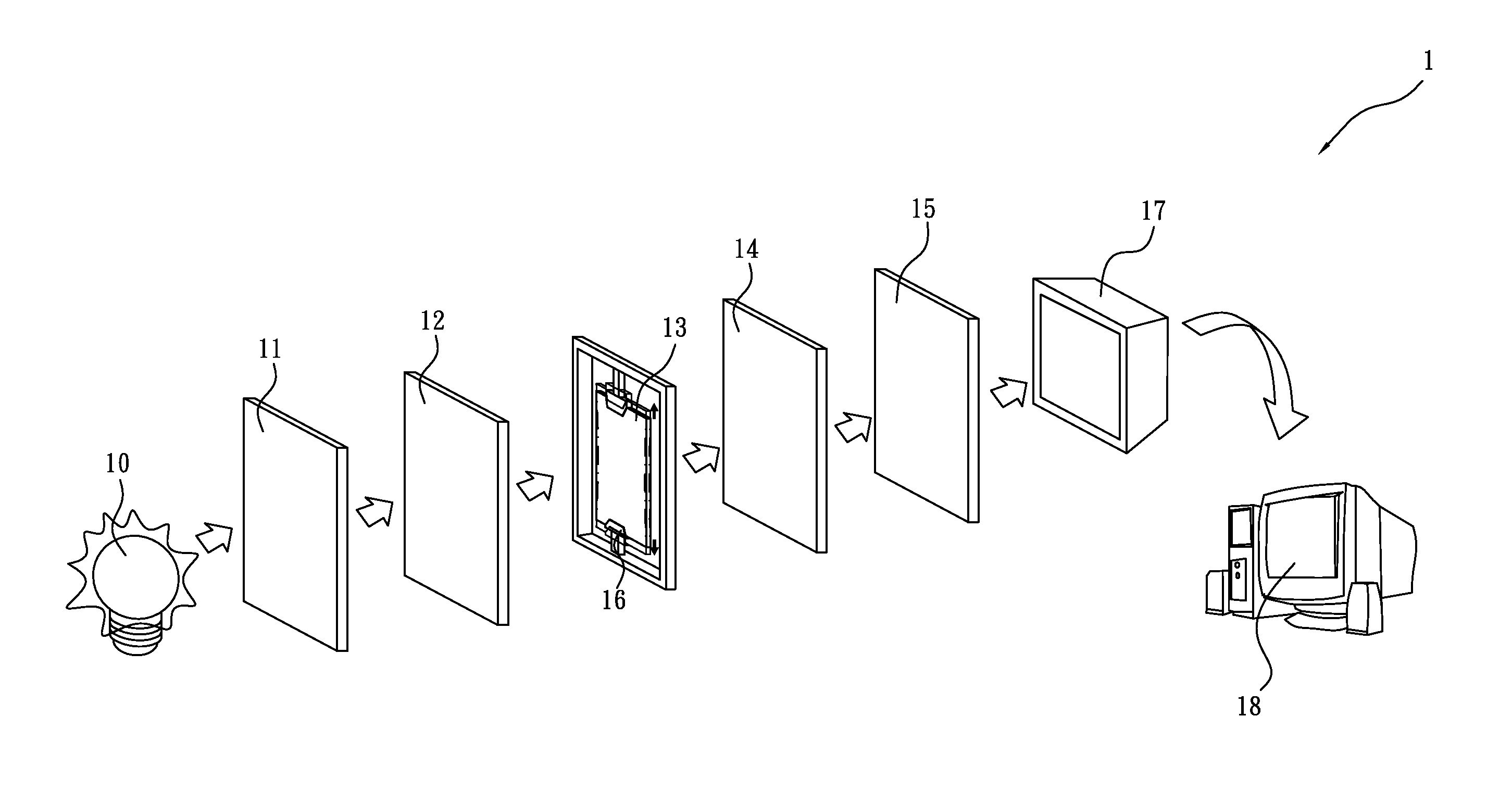
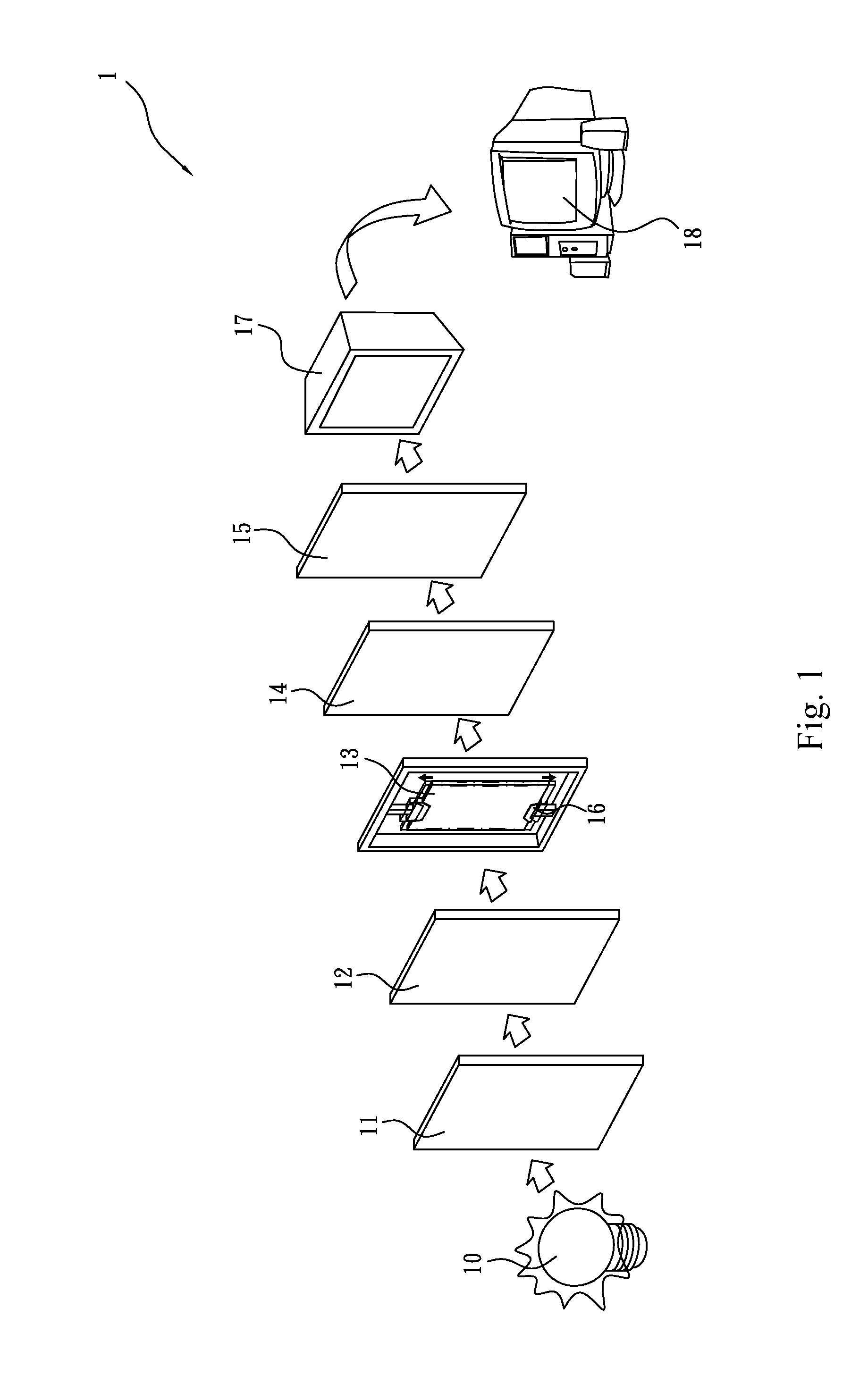
[0100]When the apparatus constructed in accordance with the present invention is used to measure the unknown and residual stress in a material to be tested, a standard material which is substantially the same as that of the material to be tested is placed between the first quarter-wave plate 12 and the second quarter-wave. The standard material 13 is then placed on the loading unit 16. After the light beam of different wavelengths from the light source 10 is projected onto the material, the resulting fraction from the standard material 13 due to stress in the standard material is sent to the spectrometer 17b for recording and thus the transmissivity spectrum under the wavelength of the light source 10 is obtained. Thereafter, the loading and light intensity recording steps are repeated to record the change relationship between the stress and the transmissivity under the wavelength of the light so...


PUM


Abstract

An apparatus for quantifying unknown stress and residual stress of a material to be tested, the material being a birefringent or temporary birefringent material, which includes a light source, a polarizer in front of the light source for converting a light beam from the light source into a beam with linear polarization, a first quarter-wave plate in front of the polarizer for generating circular polarization, a standard material, a second quarter-wave plate, an analyzer, a loading unit, a spectrometer for obtaining transmissivity spectrum of the standard material under the wavelength of the light source and a detecting module connected to the spectrometer to have the transmissivity spectrum of the material to be tested and consequently a stress quantifying formula for the standard material.

Description

CROSS-REFERENCE TO RELATED APPLICATION[0001]This application claims priority from application No. 101109034, filed on Mar. 16, 2012 in the Taiwan Intellectual Property Office.FIELD OF THE INVENTION[0002]The invention relates to an apparatus for quantifying unknown stress and residual stress of a material, and more particularly, to an apparatus for quantifying the unknown and residual stress of a material by using a polarizer in front of a light source, a first and a second quarter-wave plates to convert light beam into beams with circular polarization and / or linear polarization. respectively. A method for quantifying the unknown and residual stress of a material is also disclosed.BACKGROUND OF THE INVENTION[0003]Thin Film Transistor-Liquid Crystal Display (TFT-LCD) is one of the promising industries nowadays. The technology for manufacturing displays has been advanced with an unimaginable speed. However, during the race between technology advancement and consumers' pursuit of higher...

Claims


Application Information

Patent Timeline
IPC IPC(8): G01L1/24
CPCG01L1/24G01L1/241G01N21/23
Inventor WANG, WEI-CHUNGHUANG, CHI-HUNGSUNG, PO-CHICHEN, WEI-RENLAI, GUAN-TING
Owner NATIONAL TSING HUA UNIVERSITY
Why Eureka
Try Eureka