Process control system

Active Publication Date: 2013-09-26
YOKOGAWA ELECTRIC CORP
View PDF8 Cites 21 Cited by
  • Summary
  • Abstract
  • Description
  • Claims
  • Application Information

AI Technical Summary

Benefits of technology

[0019]When replacing an old hardware to a new hardware, the old hardware may be removed from the network and the new hardware may be connected to the network, and then, a program implementing the virtual part may be first installed into the new hardware connected to the network so as to implement a functionality of the virtual part, and next, a program implementing the operating system and a program implementing the application that had been used previously in the old hardware may be successi

Problems solved by technology

Whereas a sensor that has reached the end of its life can be individually replaced, because general-purpose electronic components are mounted in I/O cards, which are the interfaces in controllers, the life of controllers is limited to approximately 10 years, and the life of the process control system is als

Method used


Image

  • Process control system
  • Process control system
  • Process control system

Examples


first preferred embodiment

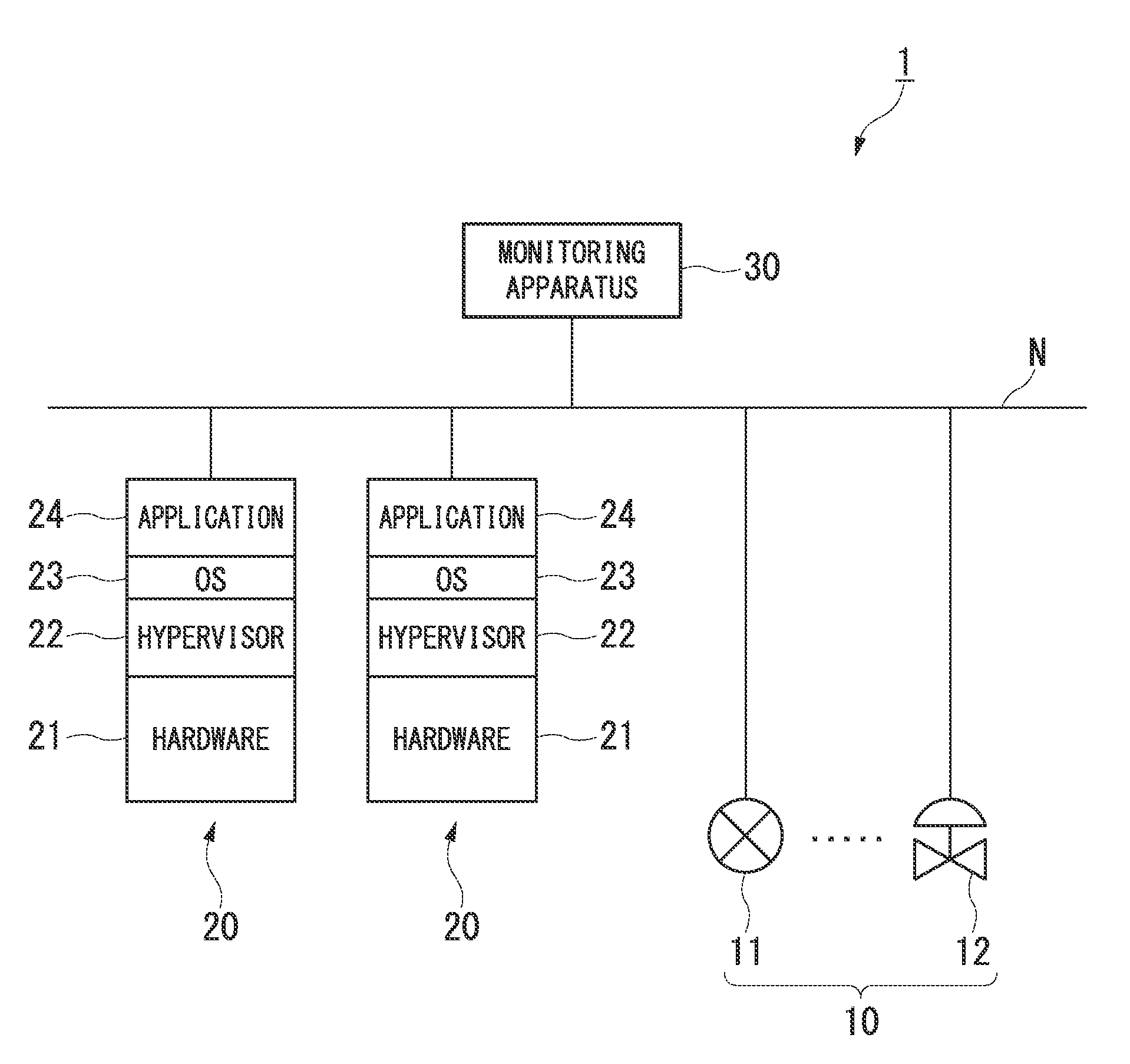
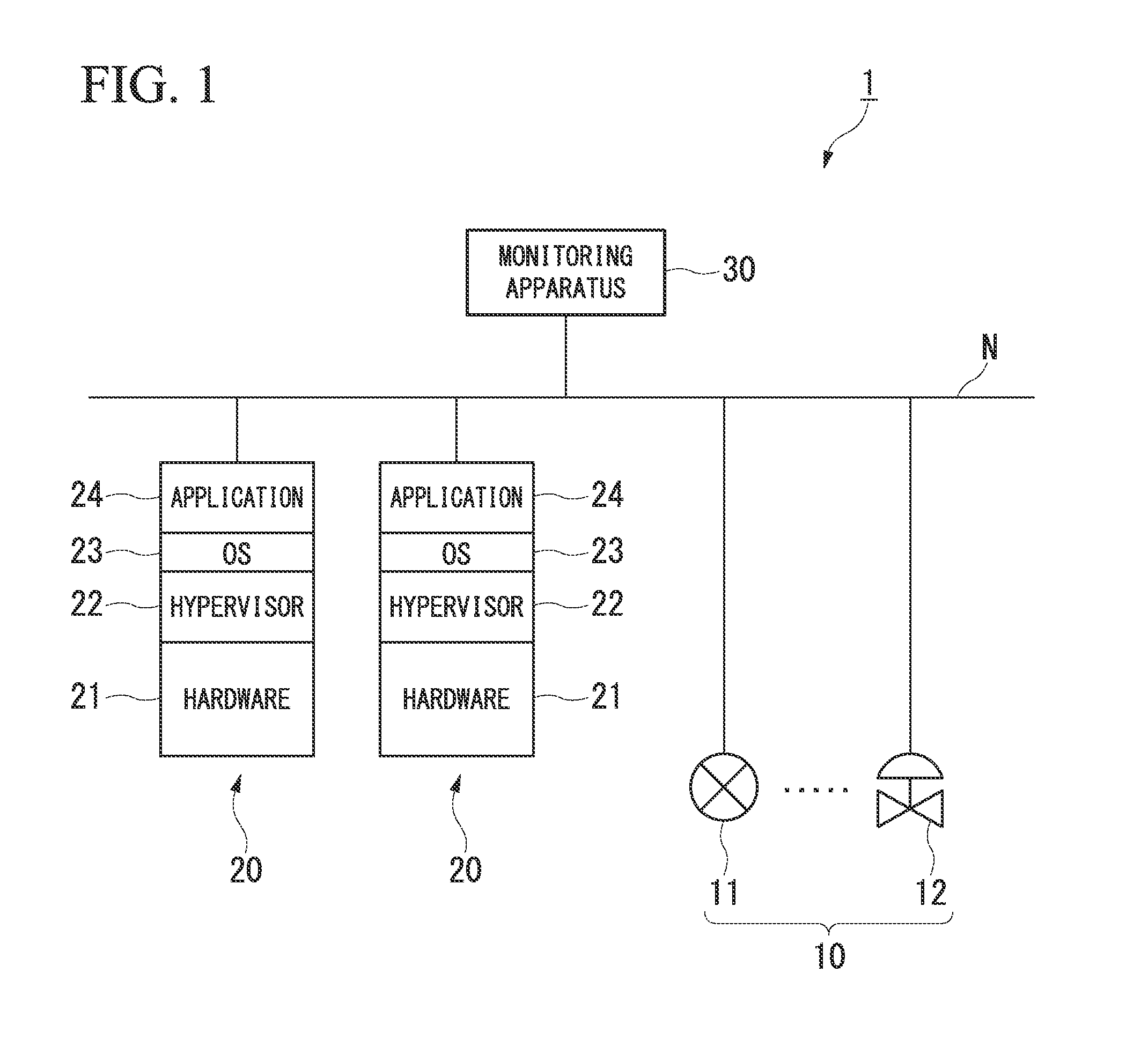
[0035]FIG. 1 is a block diagram illustrating the constitution of the main parts of a process control system in accordance with the first preferred embodiment of the present invention. As shown in FIG. 1, a process control system 1 of the first preferred embodiment has field devices 10, controllers 20, and a monitoring apparatus 30 and, by the controllers 20 controlling the field devices 10 under monitoring by monitoring apparatus 30, the industrial processes implemented in the plant (not shown) are controlled.

[0036]The field devices 10 are, for example, sensor devices such as flow gauges and temperature sensors, valve devices such as flow amount control valves and open / close valves, actuator devices such as fans, and motors, and other devices installed on-site in a plant. In FIG. 1, as an aid to understanding, of the field devices 10 installed in the plant, a sensor device 11 that measures the flow amount of a fluid and a valve device 12 that controls the flow amount of a fluid are ...

second preferred embodiment

[0050]FIG. 3 is a block diagram illustrating the constitution of the main parts of a process control system in accordance with the second preferred embodiment of the present invention. The process control system 2 of the second preferred embodiment imparts redundancy to the constitution of the process control system 1 shown in FIG. 1 for the purpose of increasing the reliability. Specifically, in place of the field devices 10 shown in FIG. 1, the process control system 2 has the field devices 40 and redundant I / O nodes 50 (input / output nodes and, in place of the network N shown in FIG. 1, has redundant networks N1 and N2, and further, in place of the controllers 20 shown in FIG. 1, has the redundant controllers 20a and 20b. The redundant I / O nodes may be referred to as input / output nodes.

[0051]Although the field devices 40, similar to the field devices 10 shown in FIG. 1, are devices that are installed on-site in a plant, they differ from the field devices 10 in FIG. 1 in that they ...

third preferred embodiment

[0067]FIG. 6 is a block diagram illustrating the constitution of the main parts of a process control system in accordance with the third preferred embodiment of the present invention. The process control system 3 of the third preferred embodiment, in addition to providing redundancy between different controllers within which a plurality of applications 24 that control the field devices 10 are caused to run, a spare controller is additionally provided for the controllers.

[0068]Specifically, the process control system 3, as shown in FIG. 6, has controllers 60a to 60c, within which a plurality of applications 24 run, and a spare controller 70, which are connected to the networks N1 and N2. For the purpose of simplification, the monitoring apparatus 30, the field devices 40, and the redundant I / O nodes 50 and the like shown in FIG. 3 have been omitted in FIG. 6.

[0069]As shown in FIG. 6, two applications 24 that run without mutual interference in the operating system 23 are implemented w...


PUM


Abstract

A process control system performing control of an industrial process implemented in a plant, may include: a network provided in the plant; a plurality of field devices connected to the network, each of the plurality of field devices is configured to perform at least one of measurement and actuation required for control of the industrial process; and a controller, connected to the network, having a virtual part configured to operate in hardware in place of hardware, and a control unit configured to operate in the virtual part and to control operations of the field devices via the network, the controller being configured to enable replacement of hardware without changing the control unit.

Description

BACKGROUND OF THE INVENTION[0001]1. Field of the Invention[0002]The present invention relates to a process control system.[0003]Priority is claimed on Japanese Patent Application No. 2012-068041, filed Mar. 23, 2012, the content of which is incorporated herein by reference.[0004]2. Description of the Related Art[0005]All patents, patent applications, patent publications, scientific articles, and the like, which will hereinafter be cited or identified in the present application, will hereby be incorporated by reference in their entirety in order to describe more fully the state of the art to which the present invention pertains.[0006]Conventionally, in plants, factories, and the like (hereinafter collectively referred to simply as plants), process control systems are implemented which control various state quantities such as pressure, temperature, and flow amount in industrial processes, and a high level of automated operation is achieved. In a conventional process control system, as...

Claims


Application Information

Patent Timeline
IPC IPC(8): G05B15/02
CPCG05B19/0421G05B15/02G06F11/1482G06F11/2097G06F11/2007G06F11/2038G06F11/20
Inventor TORIGOE, KENJI
Owner YOKOGAWA ELECTRIC CORP
Why Eureka
Try Eureka