Device for dismantling of chosen parts of assembled pallets

a technology for assembled pallets and devices, applied in metal-working equipment, manipulators, metal-working equipment, etc., can solve problems such as extreme compact solutions, and achieve the effect of improving the performance of the third dismantling station in a simple and reliable manner

Active Publication Date: 2013-10-03
YASKAWA NORDIC
View PDF0 Cites 5 Cited by
  • Summary
  • Abstract
  • Description
  • Claims
  • Application Information

AI Technical Summary

Benefits of technology

[0021]Preferably in the latter embodiment, the arms of the third dismantling station can be turned away by means of a common lever, which is controlled by a cylinder assembly. In this way the arms can be moved away in an extremely simple and reliable manner when the services of third dismantling station are not needed.
[0022]In order to improve the performance of the third dismantling station, such as when a stringer board is so b...

Problems solved by technology

This can lead to an ...

Method used


Image

  • Device for dismantling of chosen parts of assembled pallets
  • Device for dismantling of chosen parts of assembled pallets
  • Device for dismantling of chosen parts of assembled pallets

Examples


first embodiment

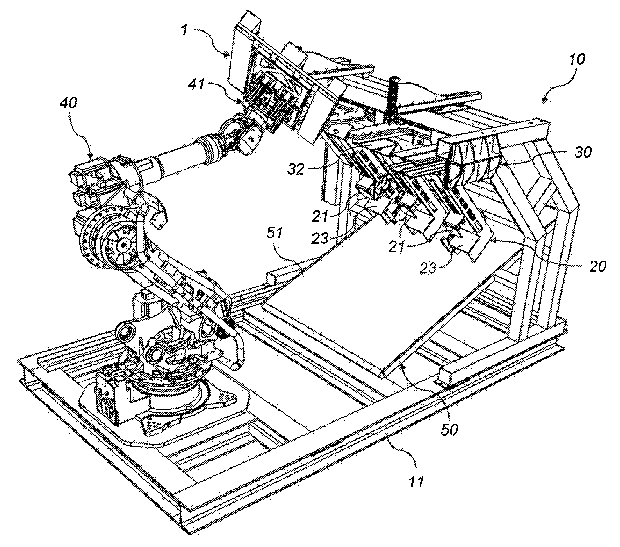
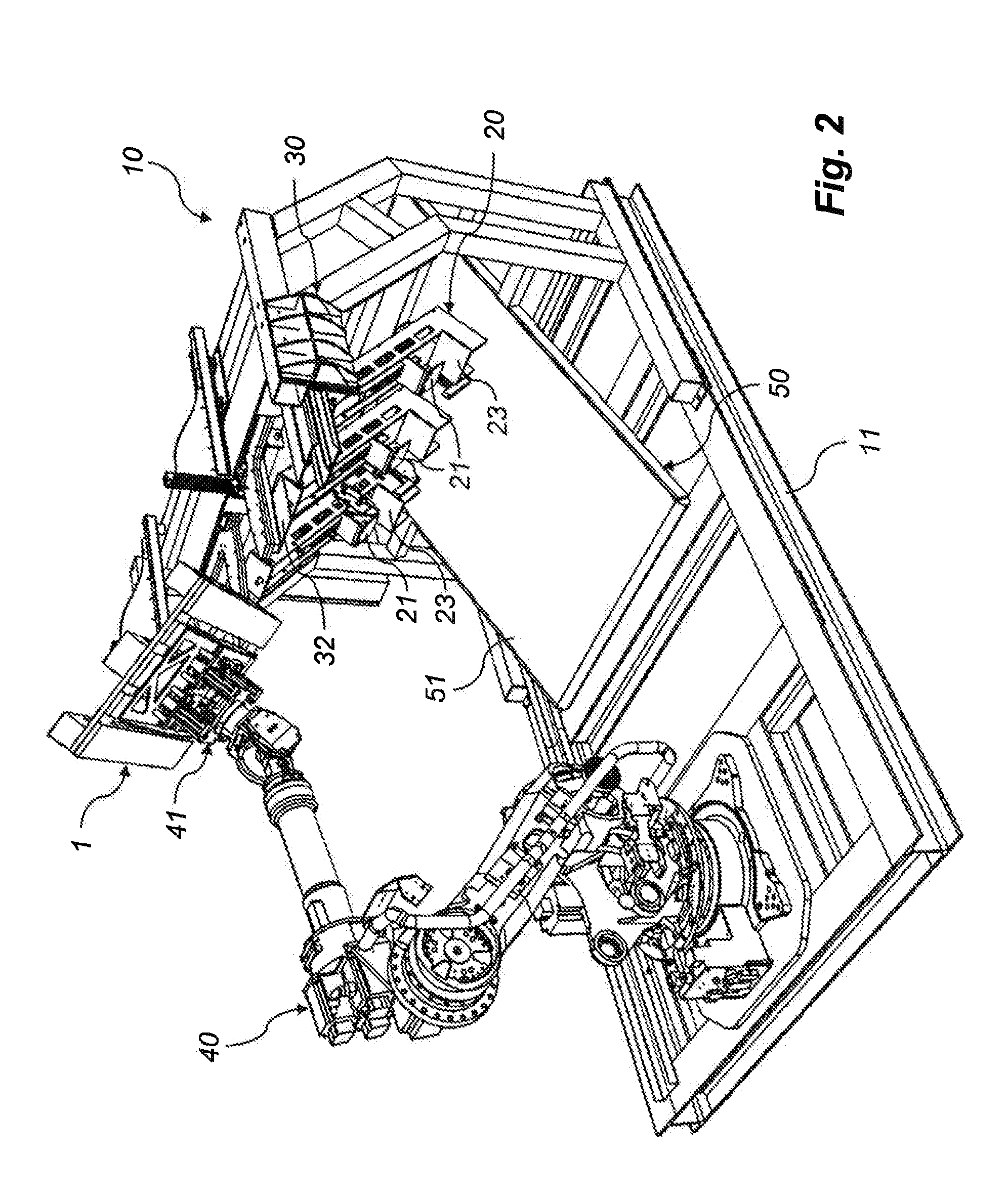
[0035]As can be seen the robot 40 of FIG. 2 is mounted on a support frame 11. According to the device according to the invention, on the same support frame 11 two so-called dismantling stations are to be found, namely a first lower dismantling station 20 and a second upper dismantling station 30. In addition, an output feeder 50, that includes a conveyor 51, is mounted on the support frame 11 under both said dismantling stations 20, 30. The purpose of the output feeder 50 is to use the conveyor belt 51 to catch and feed parts dismantled from pallets out of the device 10, and thus to keep the device free from such parts in order to obtain non-disrupted operation.

[0036]The first and, as shown, preferably lower dismantling station 20 comprises three knifes 21, which are arranged in a common plane and at center distances in relation to each other corresponding to the center distances of the three blocks 8 along a bottom board 6 of a pallet 1. As can be seen, the knifes 21 are directed o...

second embodiment

[0045]The device 10 of FIG. 6 comprises a third dismantling station 60, in which a pallet 1 is insertable and which, like the other two dismantling stations 20, 30 (not shown in FIG. 6), the robot 40 and the output feeder 50, is carried by the support frame 11 of the device 10. Thus, there the aforementioned advantages of a so-called factory in a box are at hand even with the The third dismantling station 60 comprises an inclined chute 61, that has an upper end edge 62 and a lower end edge 63, that connects to the conveyor 51 of the output feeder 50. Along the upper end edge 62 there are two arms 64 projecting from the plane of the chute 61, wherein said arms can be turned away by means of a cylinder assembly 65, that cooperates with a lever mechanism 66, when services of the third dismantling station 60 are not needed, namely to serve as a catch for extracting by the robot 40 of a stringer board 9, previously separated by means of the second dismantling station 30.

[0046]It has sho...


PUM

PropertyMeasurementUnit
Thicknessaaaaaaaaaa
Distanceaaaaaaaaaa

Abstract

The invention concerns a device for dismantling of chosen parts of assembled pallets, said device including a support frame, that carries a first and a second dismantling station, into which pallets are insertable. The first dismantling station comprises at least one knife, which can be driven in between chosen outer parts of a base of a pallet in order to separate at least some of these parts. The second dismantling station comprises at least one knife, which can be driven in between chosen inner parts of a base of a pallet or between outer parts of a deck of a pallet in order to separate any of these parts. The device also comprises a multiple-axle robot, which is arranged to feed pallets into and out of the device and to position said pallets in relation to the knifes of both dismantling stations of the device.

Description

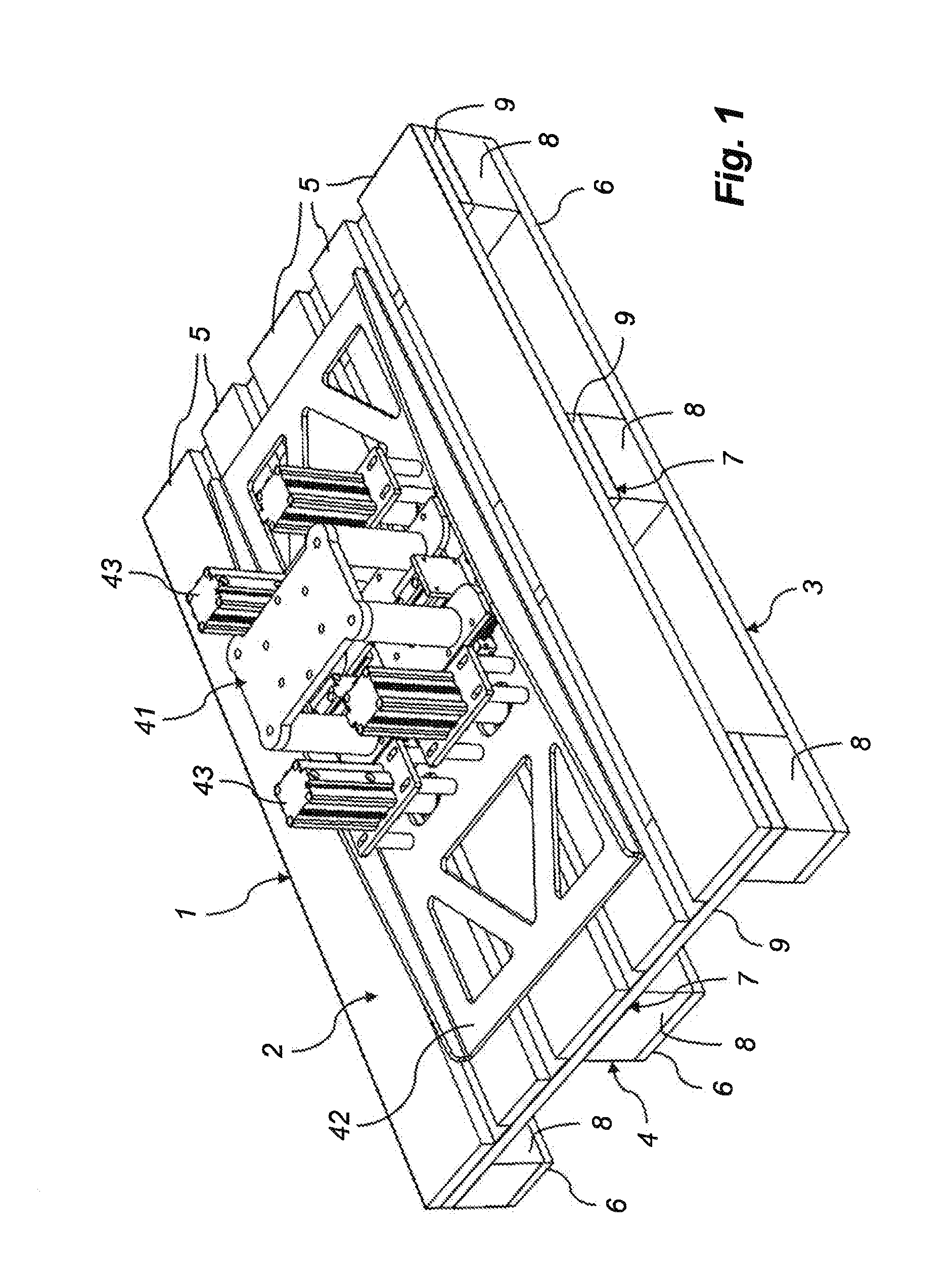
TECHNICAL FIELD[0001]The present invention relates to a device for dismantling of chosen parts of assembled pallets, each comprising a deck layer, which includes parallel deck boards arranged at given distances in relation to each other, a bottom layer, which is in parallel with the deck layer and includes parallel bottom boards, which are arranged at given distances in relation to each other, and an intermediate layer, which is arranged between the deck layer and the bottom layer and includes spacer means, which at given distances in relation to each other are connected to the deck layer and the bottom layer, said device comprising a support frame, carrying a first dismantling station, in which a pallet is insertable, wherein said first dismantling station comprises at least one knife, that has an edge, which can be driven in between a chosen spacer means and the deck layer at a chosen outer deck board, in order to separate the spacer means from the deck layer at the specified plac...

Claims


Application Information

Patent Timeline
IPC IPC(8): B23P19/04
CPCB23P19/041Y10T29/534B25J11/00
Inventor BERG, KARL-JOHANMAGNUSSON, BENGTDANIELSSON, PER
Owner YASKAWA NORDIC
Why Eureka
Try Eureka