Dryer with Air Recirculation/Heat Exchange Subassembly

a technology of air recirculation and sub-assembly, which is applied in the field of laundry dryers, can solve the problems of system complexity and cost, system damage, and system efficiency reduction, and achieve the effects of economic, efficient and practicality

Active Publication Date: 2013-10-03
ELECTROLUX HOME PROD CORP NV
View PDF6 Cites 17 Cited by
  • Summary
  • Abstract
  • Description
  • Claims
  • Application Information

AI Technical Summary

Benefits of technology

[0008]Heat recovery from recirculation and / or heat exchange arrangements in accordance with aspects of the present invention can provide an economical, efficient, and practical alternative to conventional dryer air flow arrangements.
[0010]According to another aspect of this disclosure, a heat exchanger is provided in thermal communication with both the air supply passage and the air exhaust passage. The air-to-air heat exchanger allows efficient transfer of heat energy from the warm exhaust air to the cooler supply air, and improves the dryer's ability to quickly and efficiently heat the air entering the drum. The heat exchanger may be used in conjunction with the recirculation aspects to further improve energy efficiency and heat recovery.
[0012]For example, a sharp angle or switchback feature of the recirculation passage relative to the airflow through the exhaust passage can help control the amount of air entering the recirculation passage. One or more flaps may be provided within the recirculation subassembly to direct and / or regulate the flow of recirculated air, to thereby provide an optimal ratio of fresh air to recirculated air, and thus prevent a backflow of recirculated air, air stagnation, and / or air resistance due to opposing flows. Further, the duct cross-sections may be set so that the exhaust duct / passage has a larger controlling cross-section than the recirculation duct / passage to help ensure the proper proportion of air is recirculated.
[0014]Another aim of aspects of the present invention is to provide a modular recirculated air flow system that can be easily integrated within conventional vented dryers, including at the point of manufacture or as a post-production improvement. Moreover, the components could constitute a kit for retrofitting an existing dryer.

Problems solved by technology

If too much exhaust air enters the recirculation system, efficiency may decrease.
Additionally, warm, moist recirculated air can escape into the dryer cabinet and potentially create condensation internal to the dryer unit, resulting in corrosion and other damage to the components.
Such systems can add substantial complexity and cost.
Another concern with using recirculated air is the potential fire hazard caused by lint and other debris that may remain in the recirculated air and be recirculated through the heater.
Recirculating a portion of this exhaust air back toward the heater poses the risk that accumulated lint may ignite in the heater and be carried into the drum.
However, prior proposals of dryers with air recirculation systems, or a combination of air recirculation and heat transfer, do not adequately address the practical problems of control, integration, and expense that can impede a successful implementation of these heat recovery techniques.
Additionally, excess warm, moist air may undesirably backflow into the dryer cabinet and cause harmful condensation internal to the dryer unit.

Method used


Image

  • Dryer with Air Recirculation/Heat Exchange Subassembly
  • Dryer with Air Recirculation/Heat Exchange Subassembly
  • Dryer with Air Recirculation/Heat Exchange Subassembly

Examples


Embodiment Construction

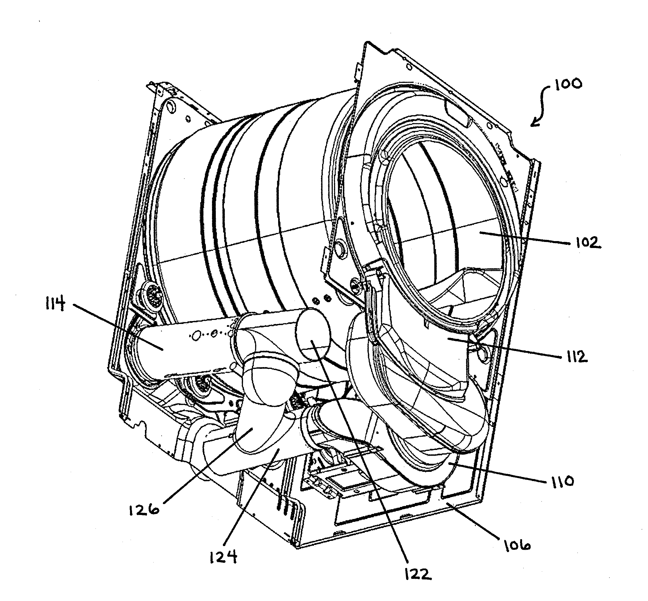
[0046]FIGS. 5-17 illustrate a vented tumble dryer 100 with an air recirculation subassembly 120 for driving a portion of warm exhaust air back toward the drum 102 of the dryer 100. In the embodiment illustrated, the recirculation subassembly 120 includes tubing / ductwork forming an air supply passage 122, air exhaust passage 124, air recirculation passage 126, and flow directing flap 130 (see FIGS. 9-10).

[0047]FIG. 4 schematically illustrates an air flow circuit, including air recirculation, of dryer 100. Fresh air 160, which is, as shown, air drawn from within the dryer cabinet 106, enters the air supply tube 122, travels through the heater tube 114 across the heater 116 (which may comprise multiple heating elements), and through a manifold 118 at a rear side of the dryer 100 (see FIG. 8) into the drum 102. The air is then pulled past a conventional lint filter 112 and into the air exhaust tube 124. The air flow is generated by a known type (e.g., centrifugal) fan / blower 110, operat...


PUM


Abstract

A laundry dryer is provided with a modular air recirculation subassembly fitted beneath a rotatable drum of the dryer. The subassembly has an air recirculation passage provided between an air supply passage and an air exhaust passage of the dryer. The air recirculation subassembly further has a flow directing flap at the juncture of the air inlet passage and the air recirculation passage to direct the recirculation air flow toward a heater and away from an inlet end of the air supply passage. The air recirculation subassembly may include a filter positioned across the air recirculation passage upstream of the heater, which filter is removable through the air exhaust passage. The subassembly may further include a heat exchanger to transfer heat from the warmer air exiting the exhaust passage to the cooler air entering the air supply passage, and a recirculation air flow regulating flap.

Description

FIELD OF THE INVENTION[0001]The present invention relates generally to laundry dryers. In particular, the invention concerns a vented laundry dryer that employs air recirculation and / or heat exchange to achieve improved efficiency.BACKGROUND OF THE INVENTION[0002]During operation, a conventional vented tumble dryer draws air from the surrounding area, heats it, and directs it into the drum of the dryer. The dryer then exhausts the air and retained water vapor through a duct to the outside. As shown in FIGS. 1-3, a known vented dryer 10 generally includes a rotatable drum 12; an air supply duct 14 which introduces air from within the dryer housing or cabinet 16 into the drum 12; a heater 26 supplied at a heater tube portion of the air supply duct 14, which heats the air introduced into the air supply duct 14; and an air exhaust duct 18 to exhaust hot air and water vapor from the dryer, typically to a duct that exhausts the air to the outside of the house or other building in which th...

Claims


Application Information

Patent Timeline
Patent Type & Authority Applications(United States)
IPC IPC(8): F26B11/02
CPCD06F58/20D06F58/02
Inventor CAVARRETTA, FRANCESCOVIGNOCCHI, MASSIMILIANOUGEL, MAURIZIOBISON, ALBERTO
Owner ELECTROLUX HOME PROD CORP NV
Why Eureka
Try Eureka