
Automotive Milling Machine, Use Of A Lifting Column Of A Milling Machine, As Well As Method For Increasing The Operating Efficiency Of A Milling Machine

a technology of milling machine and lifting column, which is applied in the direction of surface mining, roads, highway maintenance, etc., can solve the problems of reducing the service life, affecting the operation so as to increase the operating efficiency of the milling machin

Active Publication Date: 2013-10-03
WIRTGEN GMBH
View PDF6 Cites 13 Cited by
  • Summary
  • Abstract
  • Description
  • Claims
  • Application Information

AI Technical Summary

Benefits of technology

The invention is about improving the performance of a milling machine by making it more efficient. This can be achieved by modifying the lifting columns, which can be done easily and without extra space or effort. The modification allows the machine to move faster without causing excess stress or strain on the operator. This saves time and increases the machine's overall efficiency.

Problems solved by technology

5 km / h only, as the vibrations generated in travel mode can damage the mechanical components of the milling machine or can at least reduce the service life of the same.
In addition, said vibrations are also unpleasant for a machine operator.
Due to the slow speed during repositioning of the milling machine to a new operating site, the operating efficiency of the milling machine is limited.

Method used


Image

  • Automotive Milling Machine, Use Of A Lifting Column Of A Milling Machine, As Well As Method For Increasing The Operating Efficiency Of A Milling Machine
  • Automotive Milling Machine, Use Of A Lifting Column Of A Milling Machine, As Well As Method For Increasing The Operating Efficiency Of A Milling Machine
  • Automotive Milling Machine, Use Of A Lifting Column Of A Milling Machine, As Well As Method For Increasing The Operating Efficiency Of A Milling Machine

Examples


Embodiment Construction

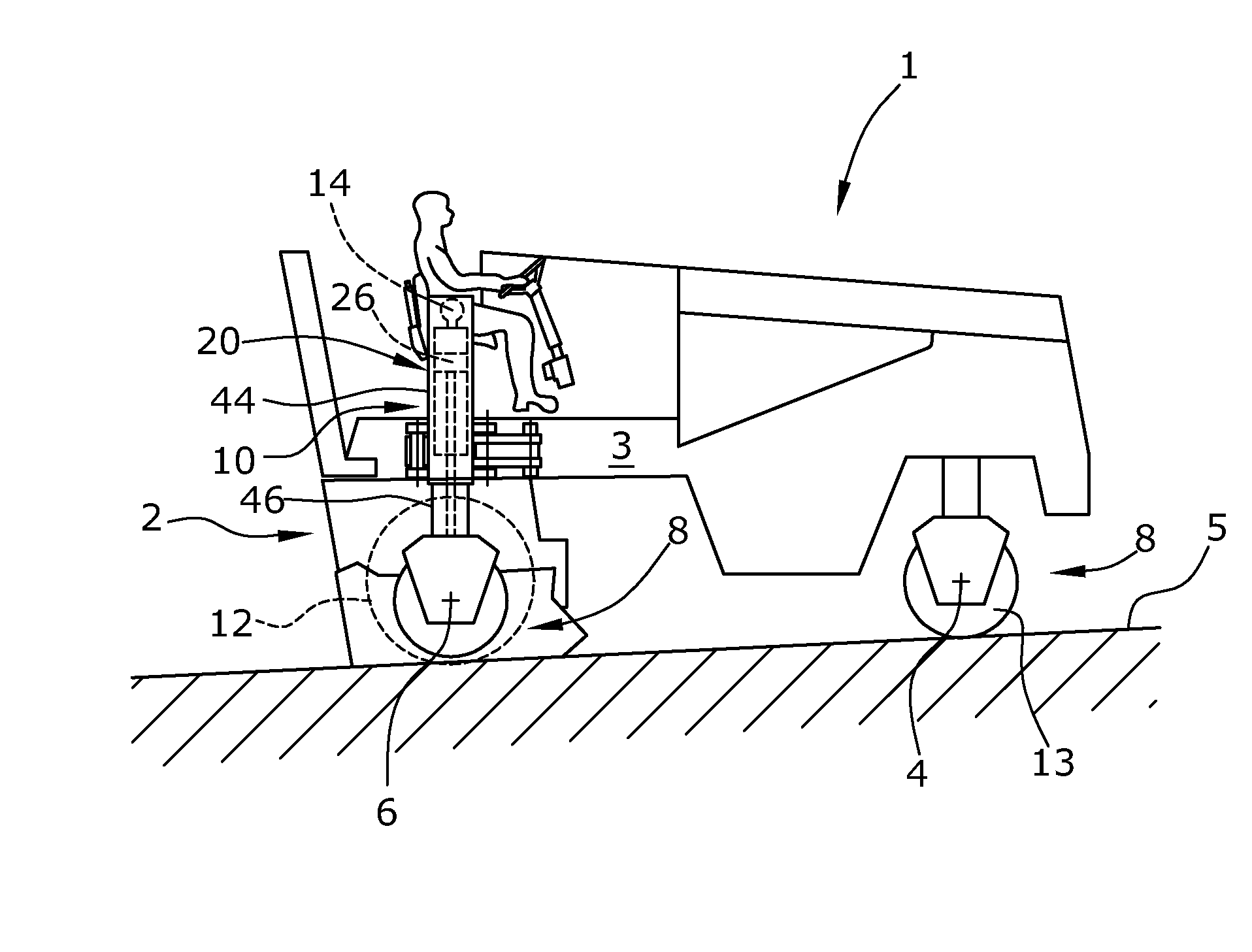
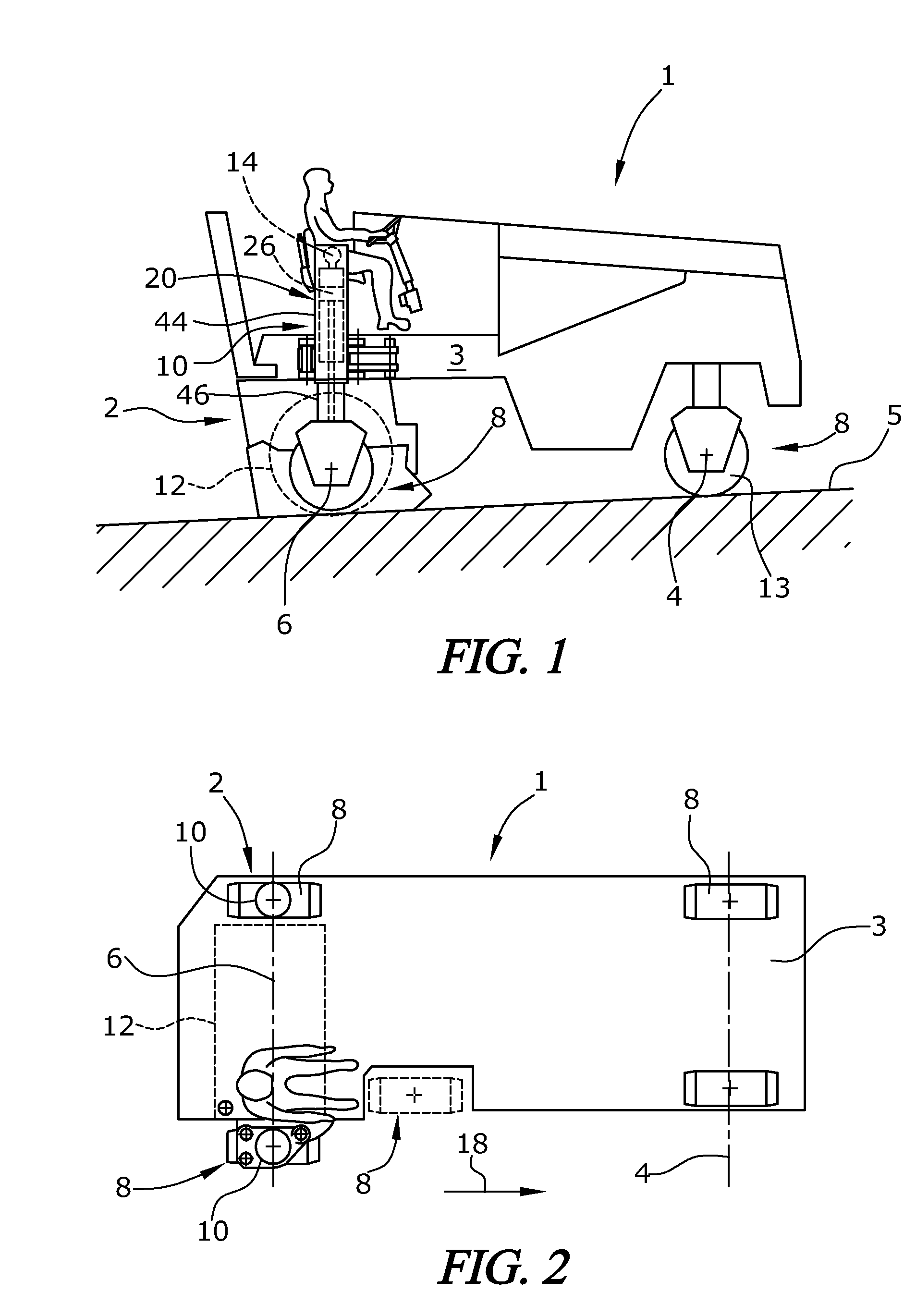
[0029]The automotive milling machine shown in FIG. 1 is a road milling machine 1 with a machine frame 3 which is supported by a chassis 2 comprising front and rear suspension axles 4,6 as seen in the direction of travel 18 with a total of no less than three suspension units 8. The suspension units 8 may be wheeled suspension units 13 or tracked suspension units, where wheeled suspension units 13 and tracked suspension units may be present together. The front suspension units 8 are steerable. The rear suspension units 8 may also be steerable.

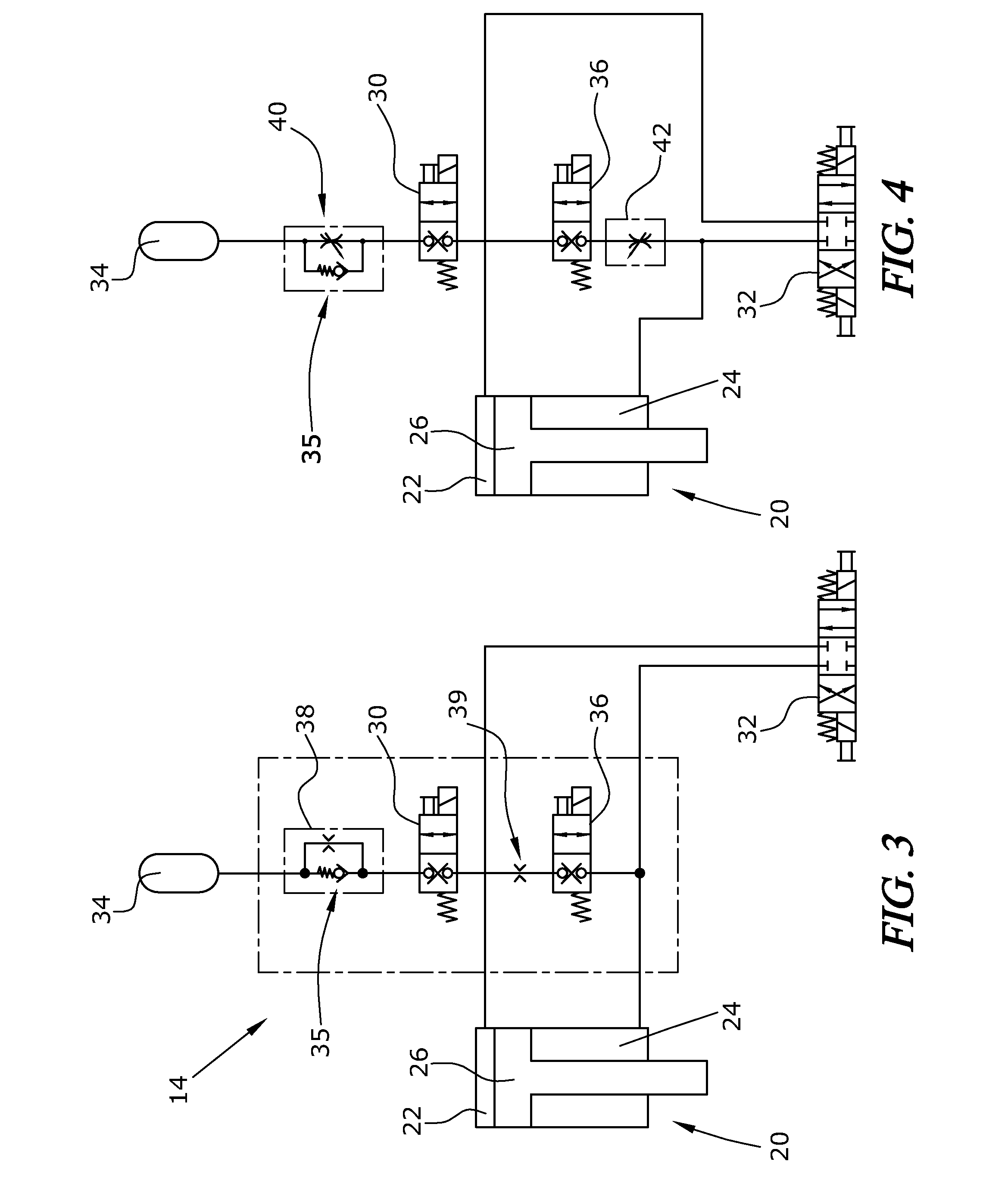
[0030]A working drum 12 is supported by the machine frame 3 where, with the working drum 12 being rigidly mounted in the machine frame 3, the milling depth can be adjusted by means of lifting columns 10. If the working drum 12 is itself mounted in the machine frame 3 in a height-adjustable fashion, the lifting columns only serve to adjust the distance of the machine frame 3 from the road surface or ground surface 5. In raised position of the work...


PUM


Abstract

An automotive milling machine, for the treatment of road surfaces or ground surfaces includes a chassis comprising front and rear suspension axles with a total of no less than three suspension units with a machine frame supported by the chassis, with lifting columns between the suspension units and the machine frame at no less than two suspension units of a suspension axle, said suspension units being transversely offset from one another in the direction of travel, and with a working drum. The working drum is adjustable to a position for driving in travel mode with the working drum raised and, in the adjusted position of the working drum at a distance from the road surface or ground surface, the lifting columns are suitable for coupling to a spring device.

Description

BACKGROUND OF THE INVENTION[0001]1. Field of the Invention[0002]The invention relates to an automotive milling machine, in particular a road milling machine, a stabilizer, a recycler or a surface miner, for the treatment of road surfaces or ground surfaces, as well as to the use of lifting columns of a milling machine, and to a method for increasing the operating efficiency of a milling machine.[0003]2. Description of the Prior Art[0004]An automotive road milling machine is known, for example, from EP 0 916 004. The road milling machine described therein comprises a chassis with front and rear suspension axles as seen in the direction of travel, wherein each suspension axle comprises two suspension units that may be comprised of wheeled suspension units and / or tracked suspension units. It is also possible for one suspension axle, preferably the front one, to comprise a single suspension unit only in smaller machines. The chassis supports the machine frame via lifting columns at no l...

Claims


Application Information

Patent Timeline
IPC IPC(8): E01C23/12
CPCE01C23/088E01C23/127
Inventor HELD, HANJOSCHAEFER, MARKUSBERNING, CHRISTIANBARIMANI, CYRUSHAEHN, GUENTER
Owner WIRTGEN GMBH
Learn More