
Wireless charging device

Inactive Publication Date: 2013-10-03
PRIMAX ELECTRONICS LTD
View PDF2 Cites 7 Cited by
  • Summary
  • Abstract
  • Description
  • Claims
  • Application Information

AI Technical Summary

Benefits of technology

The present invention provides a wireless charging device with a mechanism to absorb vibration energy and maintain the position of the coil assembly. This device includes a casing, carrying member, and first coil assembly. When the casing is fixed on a surface, the carrying member presses against the carrying part of the casing to create a balanced supporting force to maintain the specified distance between the first coil assembly and the surface. The carrying member has elastic structures to absorb vibration energy. This device allows for wireless charging of electronic devices placed on a surface. The power source provides electric energy to the first coil assembly through the circuit board, which generates a magnetic field. The second coil assembly is influenced by the magnetic field and generates an electric current. This wireless charging device can be used on moving transport tools or furniture products.

Problems solved by technology

Since the conventional electronic apparatus can only be charged by a wired transmission technology through the transmission cable and the plug, it is inconvenient to use and carry the conventional electronic apparatus, the transmission cable and the plug.
That is, if the distance is too long or too short, the wireless charging performance is deteriorated or even the wireless charging operation fails to be normally performed.
Moreover, if the wireless charging device is employed in a moving transport tool, a furniture product or any other place prone to vibration, the wireless charging device is easily shifted or damaged.
Under this circumstance, the wireless charging performance of the wireless charging device is deteriorated.
However, in a case that the wireless charging device 1 is operated in an object prone to vibration (e.g. within a vehicle), some drawbacks may occur.
Under this circumstance, the wireless charging performance is adversely affected.
Moreover, if the vibration is too serious, the wireless charging device 1 is possibly damaged.

Method used


Image

  • Wireless charging device
  • Wireless charging device
  • Wireless charging device

Examples


Embodiment Construction

[0030]For eliminating the drawbacks encountered from the prior art, the present invention provides a wireless charging device.

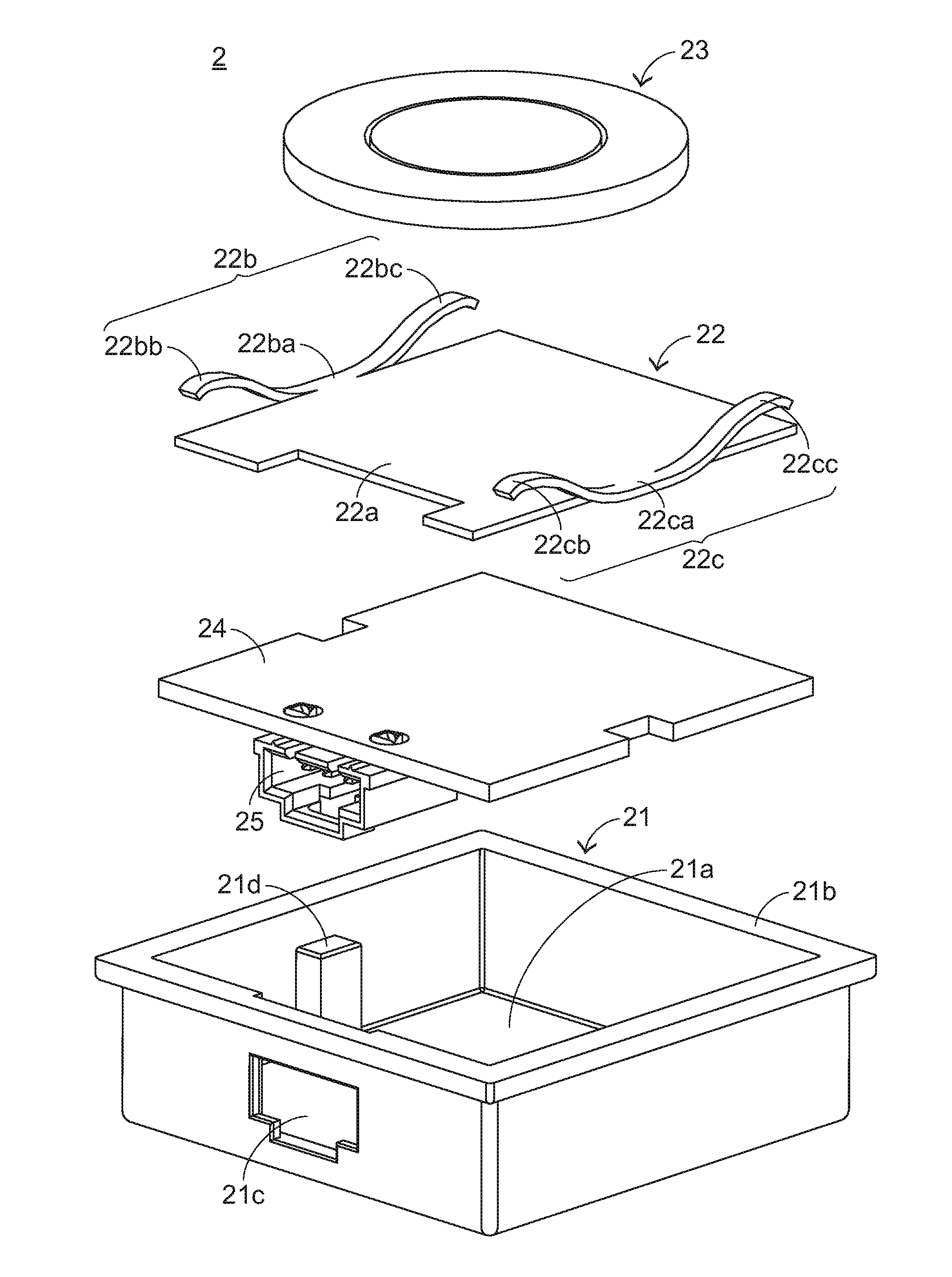
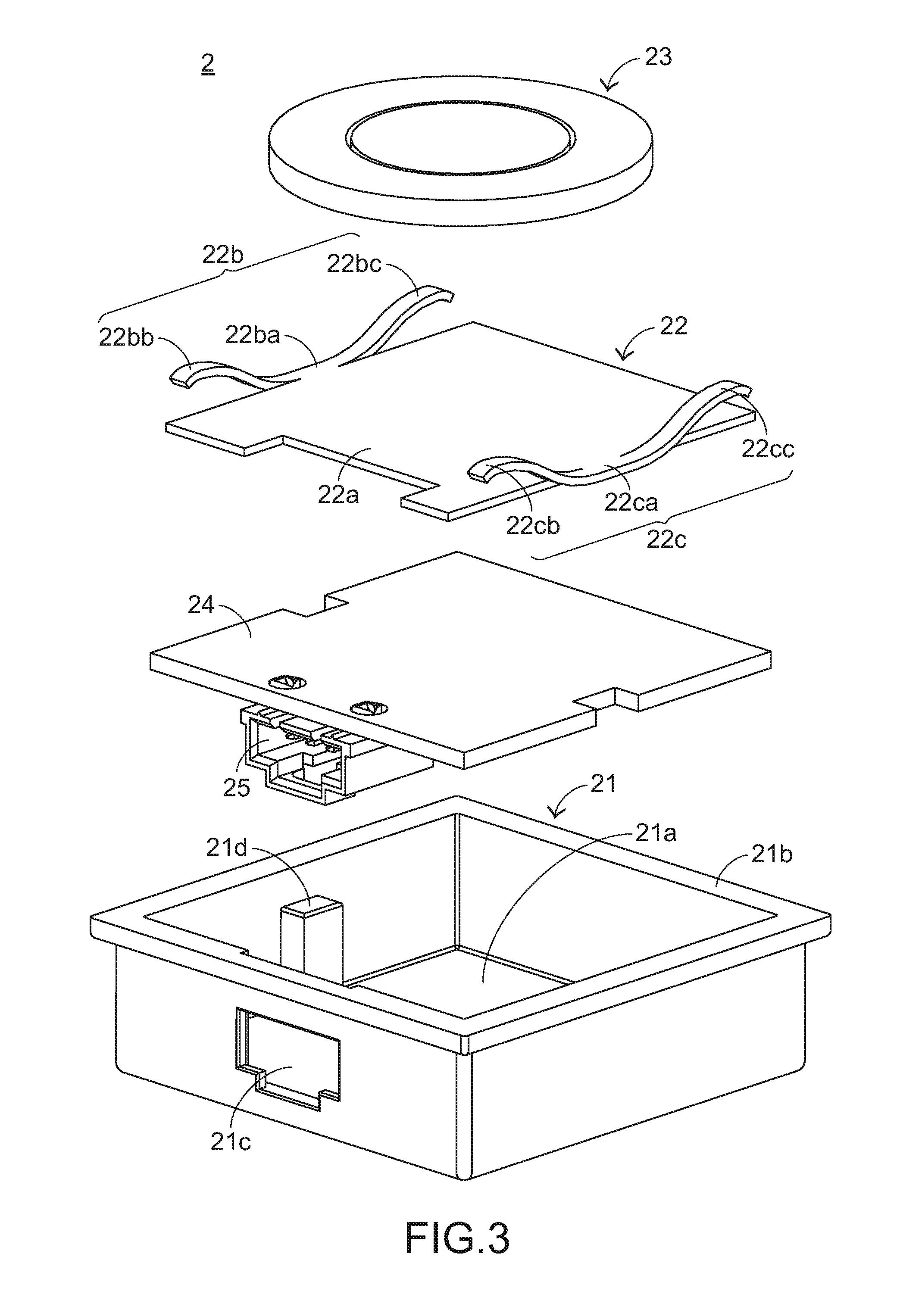
[0031]Hereinafter, the components of a wireless charging device according to an embodiment of the present invention will be illustrated with reference to FIGS. 3 and 4. FIG. 3 is a schematic exploded view illustrating a wireless charging device according to an embodiment of the present invention and taken along a first viewpoint. FIG. 4 is a schematic exploded view illustrating the wireless charging device of FIG. 3 and taken along a second viewpoint.

[0032]As shown in FIGS. 3 and 4, the wireless charging device 2 comprises a casing 21, a carrying member 22, a first coil assembly 23, a circuit board 24, and a connector 25. The casing 21 comprises a receiving space 21a, an entrance side 21b, a notch 21c, and a supporting part 21d. The supporting part 21d is disposed within the receiving space 21a. The carrying member 22 comprises a carrying plate 22a, a first e...


PUM


Abstract

A wireless charging device includes a casing, a carrying member, and a first coil assembly. The casing includes a receiving space, an entrance side, and a supporting part. The carrying member includes a carrying plate, a first elastic structure, and a second elastic structure. The supporting part is disposed within the receiving space. The carrying member is located over the supporting part. The first coil assembly is fixed on the carrying plate. When the entrance side of the casing is fixed on a first surface of an object, the supporting part is presses against the first elastic structure and the second elastic structure, allowing the first elastic structure and the second elastic structure to be pushed by the first surface of the object and subject to deformation. Consequently, a balanced supporting force is generated to maintain a specified distance between the first coil assembly and the first surface of the object.

Description

FIELD OF THE INVENTION[0001]The present invention relates to a wireless charging device, and more particularly to a wireless charging device for an electronic apparatus.BACKGROUND OF THE INVENTION[0002]For providing sufficient electric power to an electronic apparatus such as a mobile phone or a notebook computer, the electronic apparatus may be electrically connected to a power socket through a transmission cable and a plug or the electronic apparatus may be electrically connected to a computer in order to acquire the electric power. Since the conventional electronic apparatus can only be charged by a wired transmission technology through the transmission cable and the plug, it is inconvenient to use and carry the conventional electronic apparatus, the transmission cable and the plug.[0003]For solving the above drawbacks, a variety of wireless charging devices have been disclosed. When an electronic apparatus is placed on a surface of the wireless charging device, the wireless char...

Claims


Application Information

Patent Timeline
IPC IPC(8): H02J17/00H02J7/00
CPCH02J7/025H02J7/0042H02J50/10
Inventor CHEN, CHIH-HUNG
Owner PRIMAX ELECTRONICS LTD
Features
  • Generate Ideas
  • Intellectual Property
  • Life Sciences
  • Materials
  • Tech Scout
  • Unparalleled Data Quality
  • Higher Quality Content
  • 60% Fewer Hallucinations
Learn More