Capacitive touch panel with dynamically allocated electrodes
- Summary
- Abstract
- Description
- Claims
- Application Information
AI Technical Summary
Benefits of technology
Problems solved by technology
Method used
Image

Examples
second embodiment
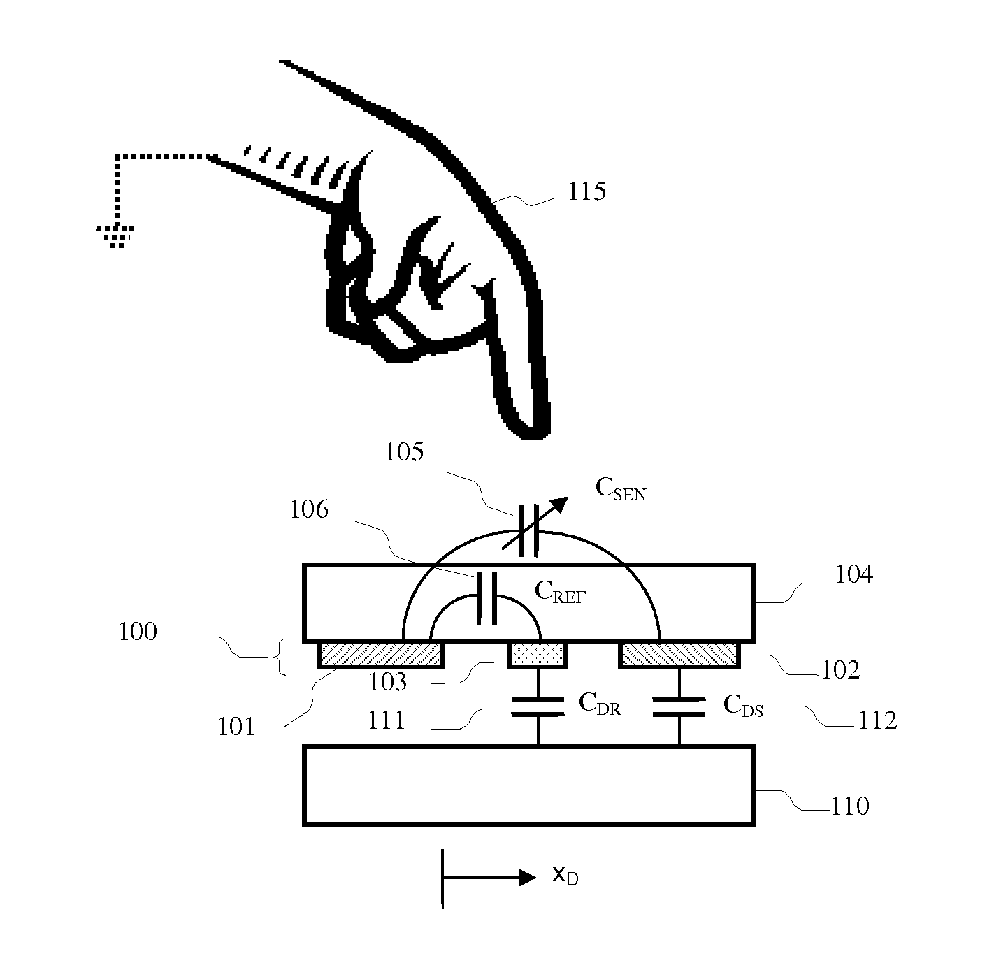
[0176]A limitation of the reference electrode design illustrated in FIG. 7A, FIG. 7B and FIG. 7C is that, even if noise injected from the display device couples equally to both the sense electrode and reference electrode, noise injected from the touching object may not. For example, depending on the location and size of the touching object, the ratio of the parasitic capacitances formed between the object and the sense and reference electrodes (COS, COR) may not be the same as the ratio of the parasitic capacitances formed between the display device and the sense and reference electrodes (CDS, CDR), i.e. COS / COR≠CDS / CDR. Further, if the areas of the sense and reference electrodes are weighted such that CDS=β·CDR then any difference in the injected noise will be multiplied by the weighting factor β in the sense circuit. Accordingly, in a touch panel device in accordance with the invention, sense and reference electrodes with improved noise immunity are provided. FIG. 11A shows an exe...
fourth embodiment
[0179]However, even though it is now only the difference between the first and second mutual coupling capacitors 105, 106 that is being measured, saturation may still occur in the sensing circuit if the baseline capacitance (i.e. the capacitance when no touching object is in the proximity of the touch panel) of the first and second mutual capacitors is significantly different—for example when the difference in baseline capacitance is similar to the maximum difference that is expected to be caused by a touching object. Although one solution to this problem is to account for this baseline by increasing the range of capacitances that may be measured, this is undesirable since it must be done by reducing the sensitivity of the sensing circuit and hence reducing the SNR. In accordance with the invention, the sense electrode and reference electrode are additionally arranged such that the baseline value of the mutual capacitance between the drive electrode and sense electrode is substantia...
fifth embodiment
[0180]In accordance with the invention, the most general embodiment of a second aspect of the invention, a mutual capacitance type touch panel device includes an electrode array comprising at least one each of a drive electrode, and a pair of matched sense electrodes. FIG. 14A shows an exemplary arrangement of the electrode array 400 with drive electrode 401 and sense electrode pair 402 which comprises a first dual-function electrode 403 and a second dual-function electrode 404. The first and second dual-function electrodes 403, 404 are arranged substantially symmetrically around each drive electrode such that the first (or second) dual-function electrode is adjacent to the drive electrode whilst the second (or first) dual-function electrode is separated from the drive electrode by the first (or second) dual-function electrode. As used herein, the term “symmetrical” refers to symmetry relative to at least one axis. The drive electrode 401 therefore forms a first mutual coupling capa...
PUM
 Abstract
Description
Claims
Application Information