

Image pickup lens
a technology of image pickup and lens, which is applied in the field of image pickup lenses, can solve the problems of reducing the size and thinning of the imaging devices built in the field, unable to recognize, and the value of the lens is approximately 3.0, so as to facilitate cost reduction and mass production
- Summary
- Abstract
- Description
- Claims
- Application Information
AI Technical Summary
Benefits of technology
Problems solved by technology
Method used
Image

Examples
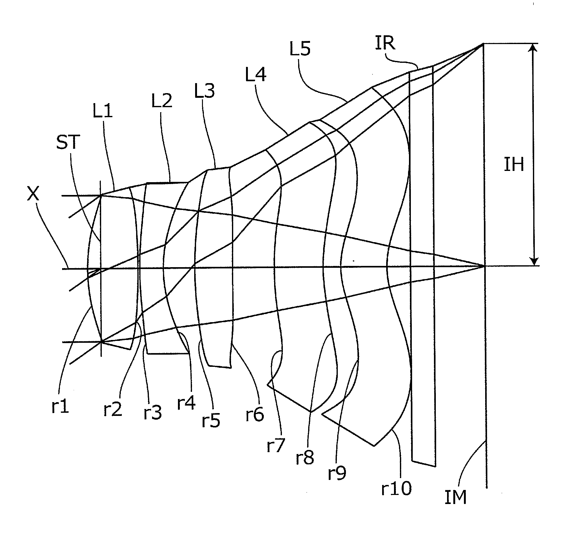
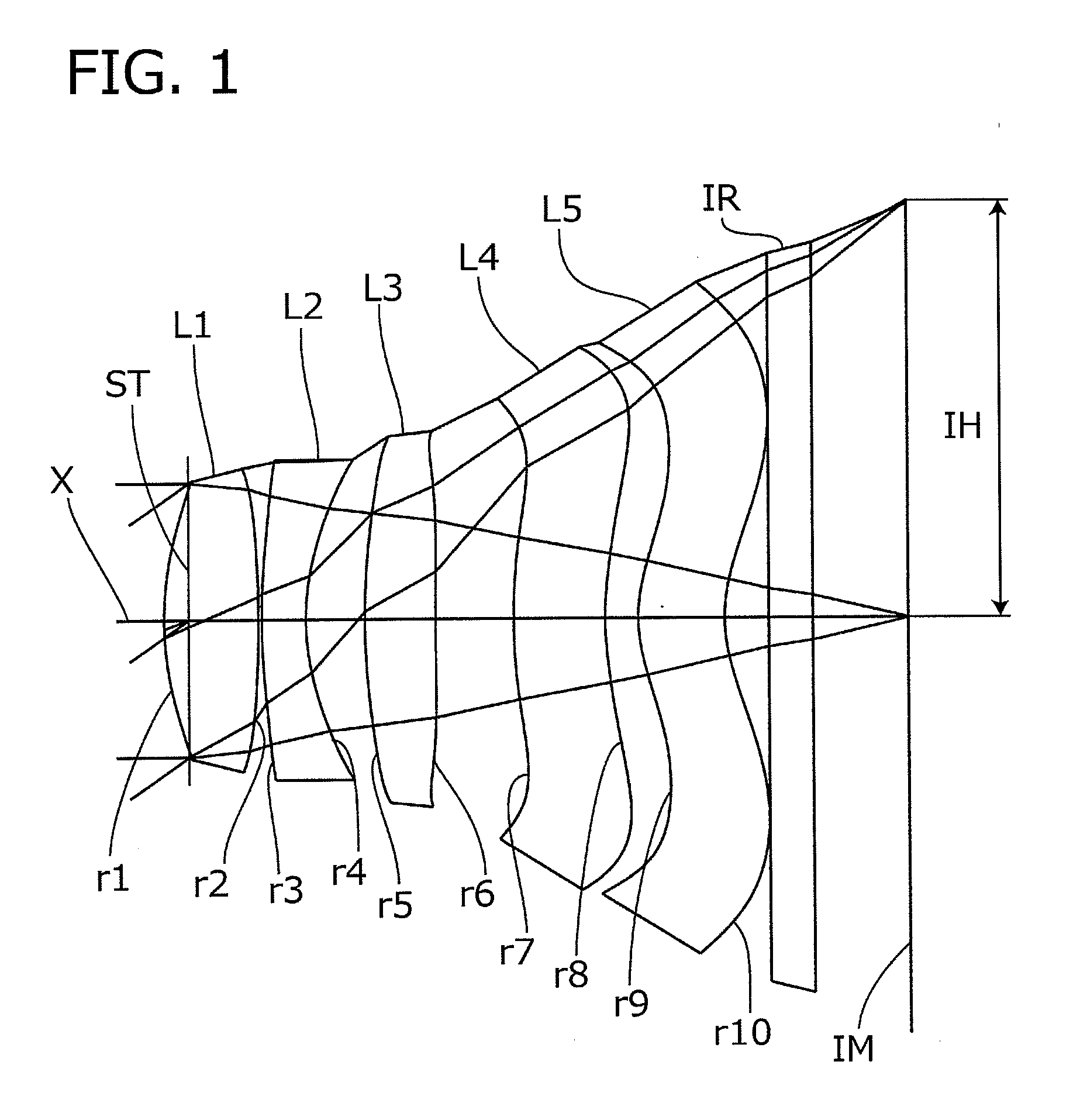
embodiment 1
[0063]Basic lens data will be shown in Table 1 below.
TABLE 1Embodiment 1Unit mmf = 4.109Fno = 2.20ω = 34.89IH = 2.856Surface dataRefractiveindexAbbe numberSurface No. iCurvature radius rSurface distance dNdνd(Object surface)InfinityInfinityStopInfinity−0.171*2.14890.6451.53556.1602*−8.21490.0233*4.26620.3021.61425.5774*1.62360.40235*4.50970.48611.53556.1606*21.18520.53657*3.94260.63141.53556.1608*1.94220.22679*0.99750.59251.53556.16010* 1.07720.3511 Infinity0.31.51764.19812 Infinity0.6068Image PlaneInfinitySingle lens dataLensStart planeFocal length113.24023−4.4223510.55547−8.007596.973Aspheric dataFirst surfaceSecond surfaceThird surfaceFourth surfaceFifth surfacek0.000E+000.000E+000.000E+000.000E+000.000E+00A4−2.117E−021.812E−02−5.379E−02−1.095E−01−2.784E−02A6−4.623E−03−7.453E−029.387E−037.311E−021.933E−02A8−8.926E−033.686E−02−1.272E−02−6.365E−02−7.745E−03A10−9.320E−03−1.230E−021.637E−022.498E−02−3.340E−03A120.000E+000.000E+000.000E+000.000E+002.097E−03A140.000E+000.000E+000.000E+...
embodiment 2
[0067]Basic lens data will be shown in Table 2 below.
TABLE 2Embodiment 2Unit mmf = 4.132Fno = 2.05ω = 34.66IH = 2.856Surface dataRefractiveindexAbbe numberSurface No. iCurvature radius rSurface distance dNdνd(Object surface)InfinityInfinityStopInfinity−0.171*2.3170.7031.53556.1602*−6.4660.0233*4.39960.32161.61425.5774*1.64940.38645*5.0320.48581.53556.1606*20.3010.50997*3.750.64181.53556.1608*2.20430.2399*1.07610.61481.53556.16010* 1.12280.3111 Infinity0.31.51764.19812 Infinity0.6672Image PlaneInfinitySingle lens dataLensStart planeFocal length113.26923−4.4563512.32547−11.651598.607Aspheric dataFirst surfaceSecond surfaceThird surfaceFourth surfaceFifth surfacek0.000E+000.000E+000.000E+000.000E+000.000E+00A4−2.099E−022.086E−02−5.400E−02−1.133E−01−2.958E−02A6−4.167E−03−7.287E−028.212E−037.166E−022.067E−02A8−6.781E−033.669E−02−1.508E−02−6.390E−02−6.801E−03A10−6.771E−03−1.165E−021.249E−022.004E−02−3.312E−03A120.000E+000.000E+000.000E+000.000E+001.848E−03A140.000E+000.000E+000.000E+000.0...
embodiment 3
[0070]Basic lens data will be shown in Table 3 below.
TABLE 3Embodiment 3Unit mmf = 4.073Fno = 2.40ω = 35.07IH = 2.856Surface dataRefractiveindexAbbe numberSurface No. iCurvature radius rSurface distance dNdνd(Object surface)InfinityInfinityStopInfinity−0.131*2.174670.6021.53556.1602*−6.923850.02353*4.002540.28741.61425.5774*1.568020.3975*6.608490.42591.53556.1606*−197.9730.57037*3.73030.57531.53556.1608*2.56580.29259*1.13170.60421.53556.16010* 1.07320.3111 Infinity0.31.51764.19812 Infinity0.6559Image PlaneInfinitySingle lens dataLensStart planeFocal length113.15523−4.3563511.92047−18.5025914.828Aspheric dataFirst surfaceSecond surfaceThird surfaceFourth surfaceFifth surfacek0.000E+000.000E+000.000E+000.000E+000.000E+00A4−2.275E−022.199E−02−6.964E−02−1.369E−01−4.238E−02A6−5.843E−04−8.795E−021.447E−028.867E−021.425E−02A8−2.539E−025.423E−02−3.991E−03−7.082E−02−7.989E−03A10−1.798E−03−1.989E−021.284E−022.302E−022.170E−03A120.000E+000.000E+000.000E+000.000E+002.933E−03A140.000E+000.000E+0...
PUM
 Abstract
Description
Claims
Application Information