
Method and System for Pilot-Based Time Domain Phase Noise Mitigation for Coherent Receiver

a time domain and coherent receiver technology, applied in the field of coherent receivers, can solve the problems of laser phase noise (pn) and nonlinear impairment, the overall phase noise at the coherent receiver is one of the major limitations of the transmission system, and the effect of finding cp

Active Publication Date: 2013-10-03
NEC CORP
View PDF4 Cites 22 Cited by
  • Summary
  • Abstract
  • Description
  • Claims
  • Application Information

AI Technical Summary

Benefits of technology

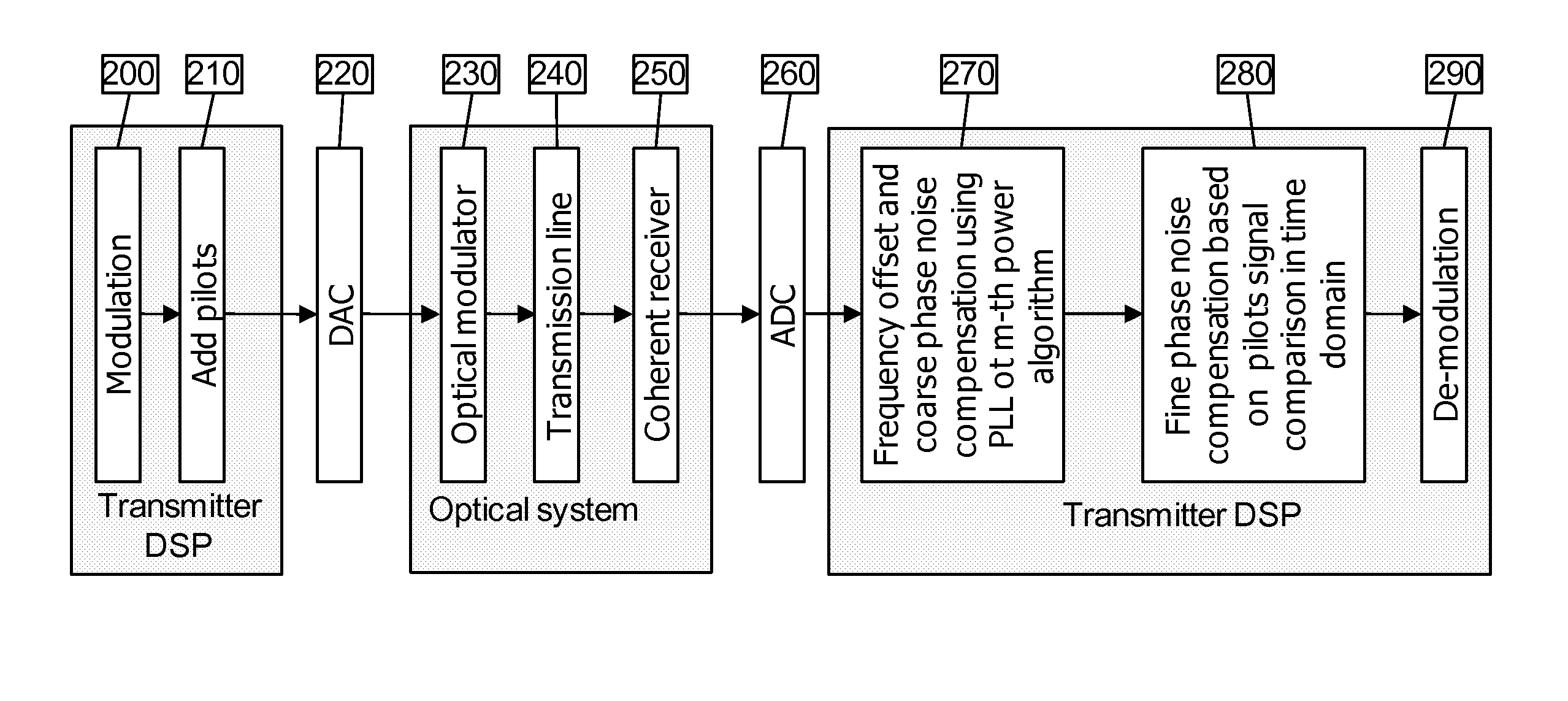
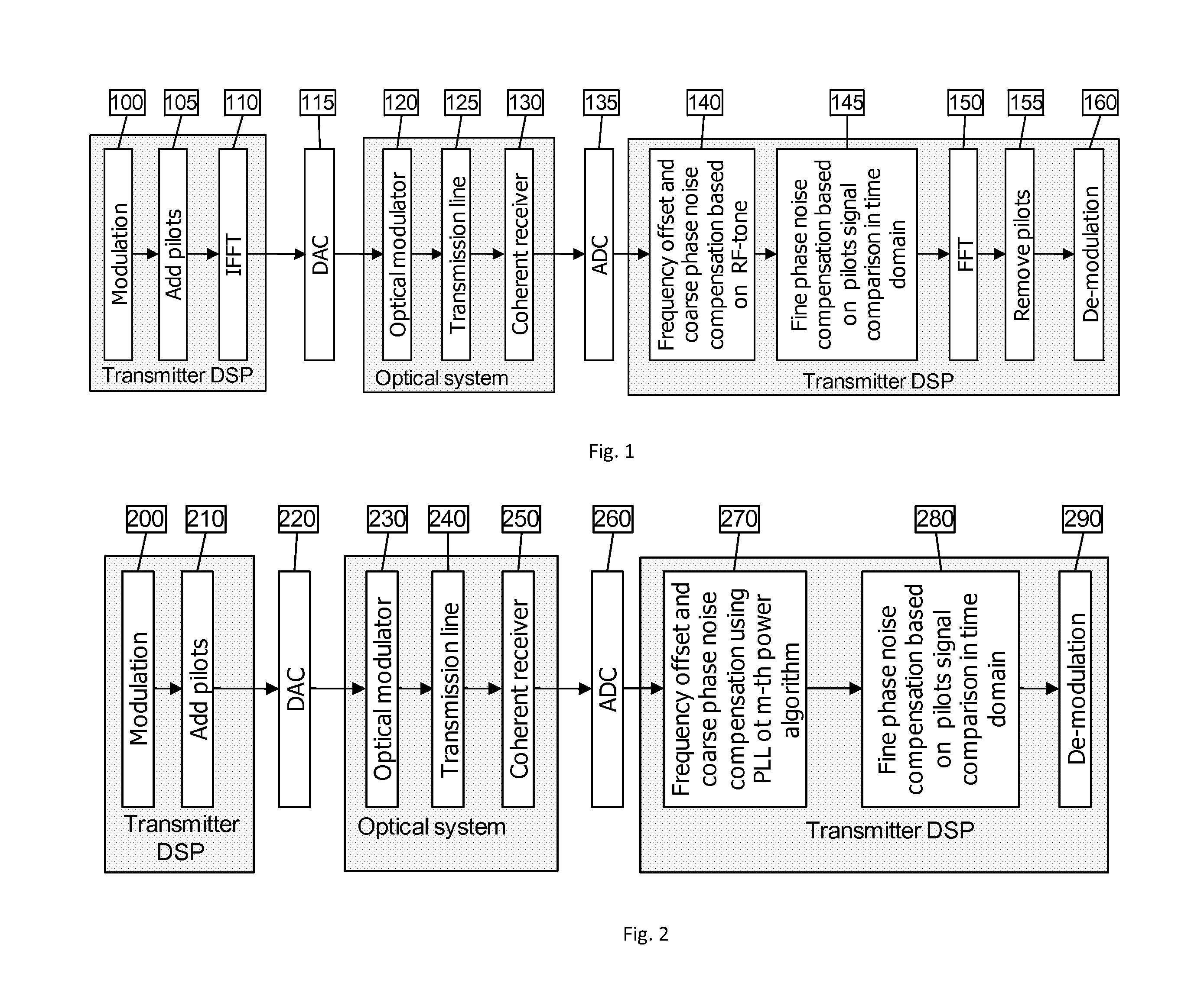
The present invention provides a method and system for reducing phase noise in a coherent receiver used in OFDM or single carrier based transmission systems. The technical effects of the invention include applying a frequency offset and coarse phase noise compensation, based on a radio frequency RF tone or using a phase lock loop PLL m-th power procedure, responsive to a signal from a digital signal processed transmission with an added pilots signal over an optical system. Additionally, fine phase noise compensation is performed by comparing the pilots signal in a time domain and removing the pilots. The system also includes a filter for removing the pilots and a demodulator for demodulating the remaining pilotless signal.

Problems solved by technology

One main challenge with using a coherent detecter is its sensitivity for laser phase noise (PN) and nonlinear impairments.
The overall phase noise at the coherent receiver is one of the major limitations of transmission system.
However, this proposed method requires accurate channel matrix to reduce the phase noise which may not be available before the phase noise is completely removed.
Other prior works used pilots to estimate phase noise in frequency domain, but they could only find CPE.
A further prior work used optical phase lock loop to reduce the phase noise, but the system complexity and cost would higher due to the feedback circuit.

Method used


Image

  • Method and System for Pilot-Based Time Domain Phase Noise Mitigation for Coherent Receiver
  • Method and System for Pilot-Based Time Domain Phase Noise Mitigation for Coherent Receiver
  • Method and System for Pilot-Based Time Domain Phase Noise Mitigation for Coherent Receiver

Examples


Embodiment Construction

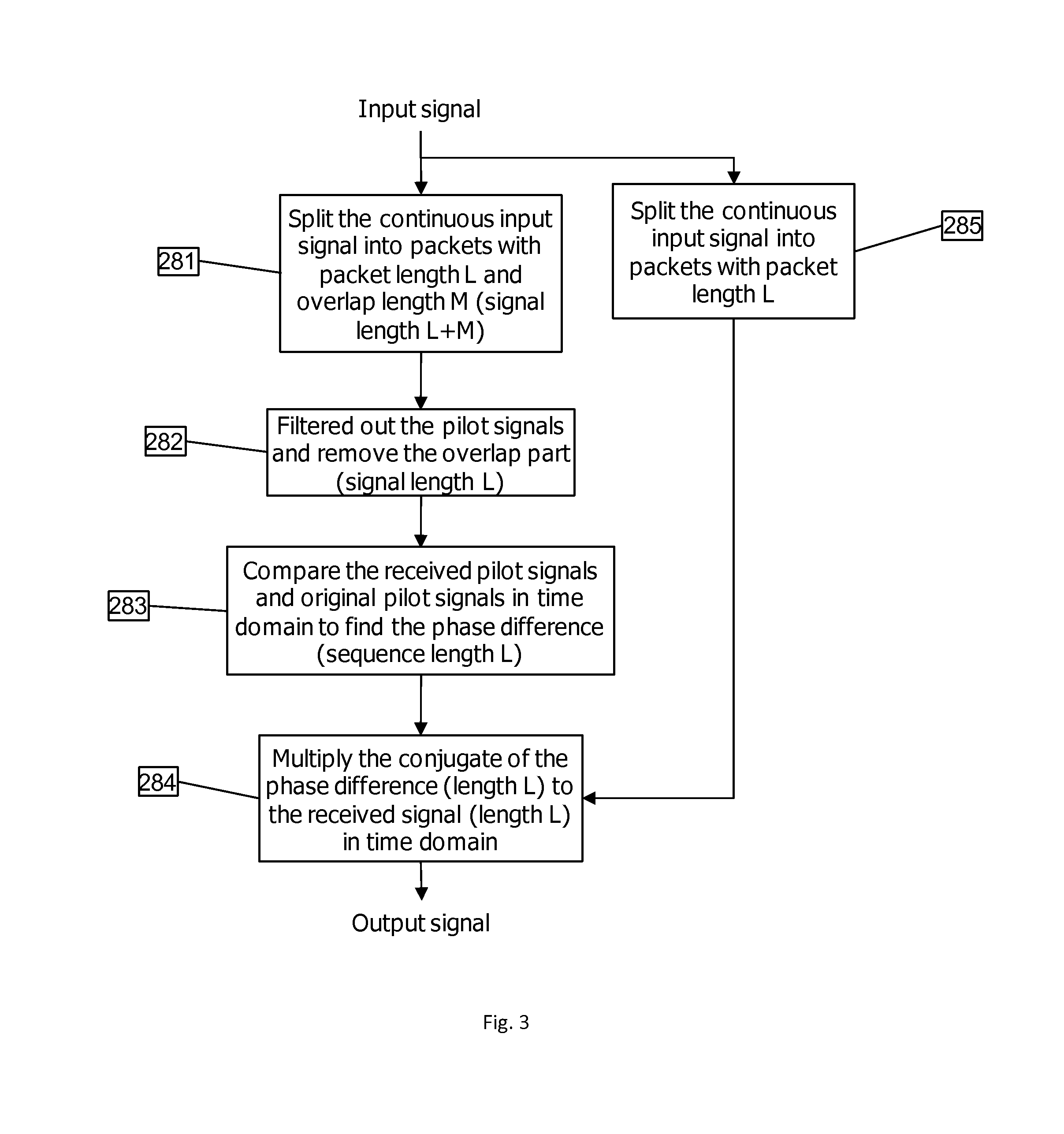
[0013]The present invention is directed to reducing phase noise by two steps: 1) for a multi-carrier (OFDM) system, step i): an RF-tone is used to remove frequency offset and to perform coarse carrier recovery, and step ii): the received pilot subcarriers are filtered out and compared with the transmitted pilots in time domain to estimate carrier phase fluctuation; and 2) for a single-carrier system, step i): phase-lock loop (PLL) or an m-th power algorithm is used to remove frequency offset and to perform coarse carrier recovery, and step ii) the received pilot subcarriers are filtered out and compared with the transmitted pilots in time domain to estimate carrier phase fluctuation.

[0014]Turning now to the diagram of FIG. 1, there is shown an exemplary diagram of an orthogonal frequency division multiplexing OFDM transmission system with pilot based phase noise mitigation, in accordance with the invention. A digital signal processor DSP transmitter, with modulation 100, add pilots ...


PUM


Abstract

A method for phase noise mitigation for a coherent receiver in either an OFDM or single carrier based transmission system including applying a frequency offset and coarse phase noise compensation based on a radio frequency RF tone or using a phase lock loop PLL m-th power procedure, responsive to a signal from a digital signal processed transmission with an added pilots signal over an optical system, applying fine phase noise compensation based on comparison of the pilots signal in a time domain, removing the pilots, and demodulating the remaining pilotless signal.

Description

RELATED APPLICATION INFORMATION[0001]This application claims priority to provisional application No. 61 / 618,898 filed Apr. 2, 2012, the contents thereof are incorporated herein by referenceBACKGROUND OF THE INVENTION[0002]The present invention relates generally to coherent receivers, and more particularly, to a pilot-based time domain phase noise mitigation for a coherent receiver.[0003]One main challenge with using a coherent detecter is its sensitivity for laser phase noise (PN) and nonlinear impairments. Laser phase noise is caused by the uncorrelated local oscillator (LO) laser. The unstable wavelength difference between the LO and the signal behaves like a random phase noise for the received signal of the coherent receiver. The fiber non-linearity phase noise is mainly caused by the self-phase modulation (SPM) and Cross-phase modulation (XPM). Those distortions will contribute both to the phase and amplitude of the received signal. The overall phase noise at the coherent receiv...

Claims


Application Information

Patent Timeline
Patent Type & Authority Applications(United States)
IPC IPC(8): H04L7/00
CPCH04L27/2697H04L7/0079H04L2027/0026H04L27/26H04L27/2272H04L27/2671H04L27/223H04B10/6165H04B2210/075H04L27/2675H04L27/2657
Inventor QIAN, DAYOUWANG, TING
Owner NEC CORP
Learn More