
Total-internal-reflection fiber optic interface modules with different optical paths and assemblies using same

a fiber optic interface module and optical path technology, applied in the field of fiber optic interface modules and assemblies, can solve the problems of limiting cable flexibility and increasing costs

Active Publication Date: 2013-10-03
CORNING OPTICAL COMM LLC
View PDF16 Cites 57 Cited by
  • Summary
  • Abstract
  • Description
  • Claims
  • Application Information

AI Technical Summary

Benefits of technology

The patent describes a fiber optic interface module that can support two optical fibers and interface with active photo-devices. The module has a ridge with a top and bottom surface, and a cavity that defines a total-internal-reflection mirror. The module also has first and second lens surfaces that are aligned with the optical fibers and the active photo-devices. The technical effects of the invention include misalignment tolerances of ±20 microns for the optical fibers and the active photo-devices, and coupling efficiencies of 85% or greater. The invention also includes a printed circuit board and integrated circuit chips to support the active photo-devices. The optical-electrical connector includes the fiber optic interface module and a contact assembly electrically interfaced with the printed circuit board. The invention provides a reliable and efficient solution for optical-fiber interface applications.

Problems solved by technology

At such high data rates, traditional copper cables have limited transmission distance and may be relatively large, thereby limiting cable flexibility and increasing expense.

Method used


Image

  • Total-internal-reflection fiber optic interface modules with different optical paths and assemblies using same
  • Total-internal-reflection fiber optic interface modules with different optical paths and assemblies using same
  • Total-internal-reflection fiber optic interface modules with different optical paths and assemblies using same

Examples


Embodiment Construction

[0068]The present disclosure relates to fiber optic interface modules and assemblies, and in particular to such modules and assemblies wherein the module employs total internal reflection and folded source and detector optical paths within the module body.

[0069]Example embodiments of the fiber optic interface module are first discussed, followed by exemplary embodiments of fiber optic interface assemblies that employ the fiber optic interface module. Example configurations for the source and detector lenses associated with the fiber optic interface module and transmit and receive channels are then described in connection with source and detector optical systems.

Fiber Optic Interface Module

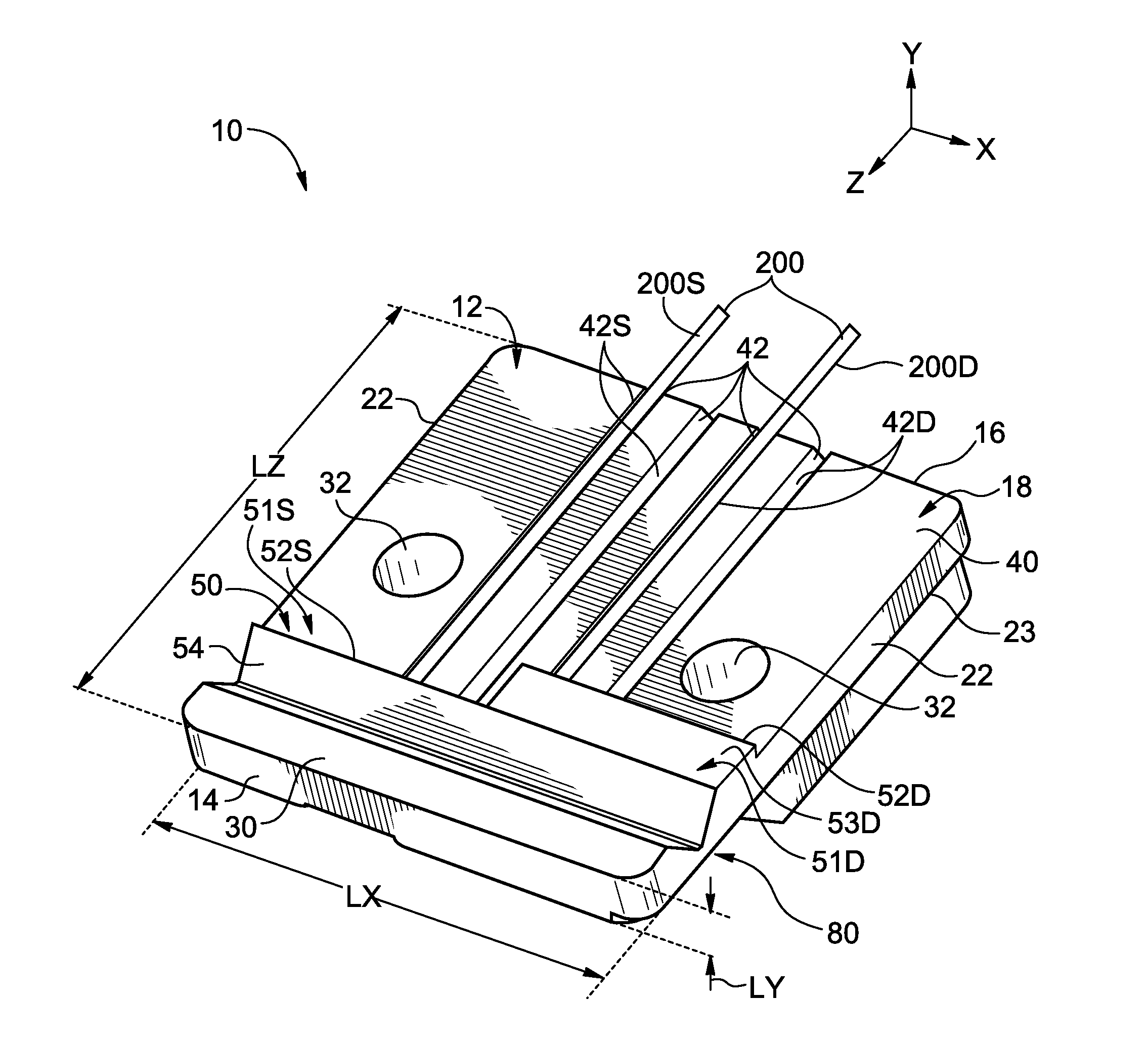
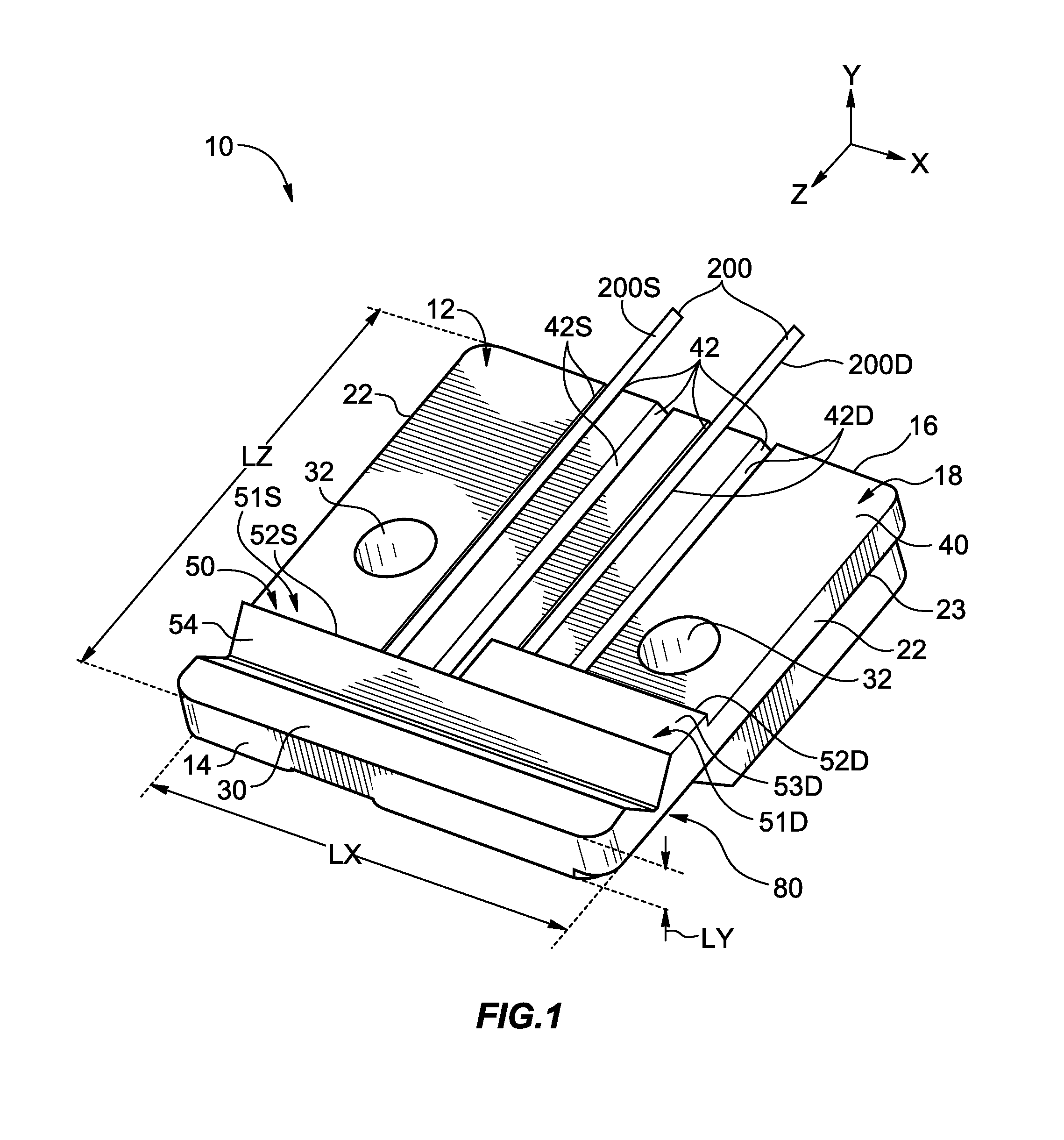
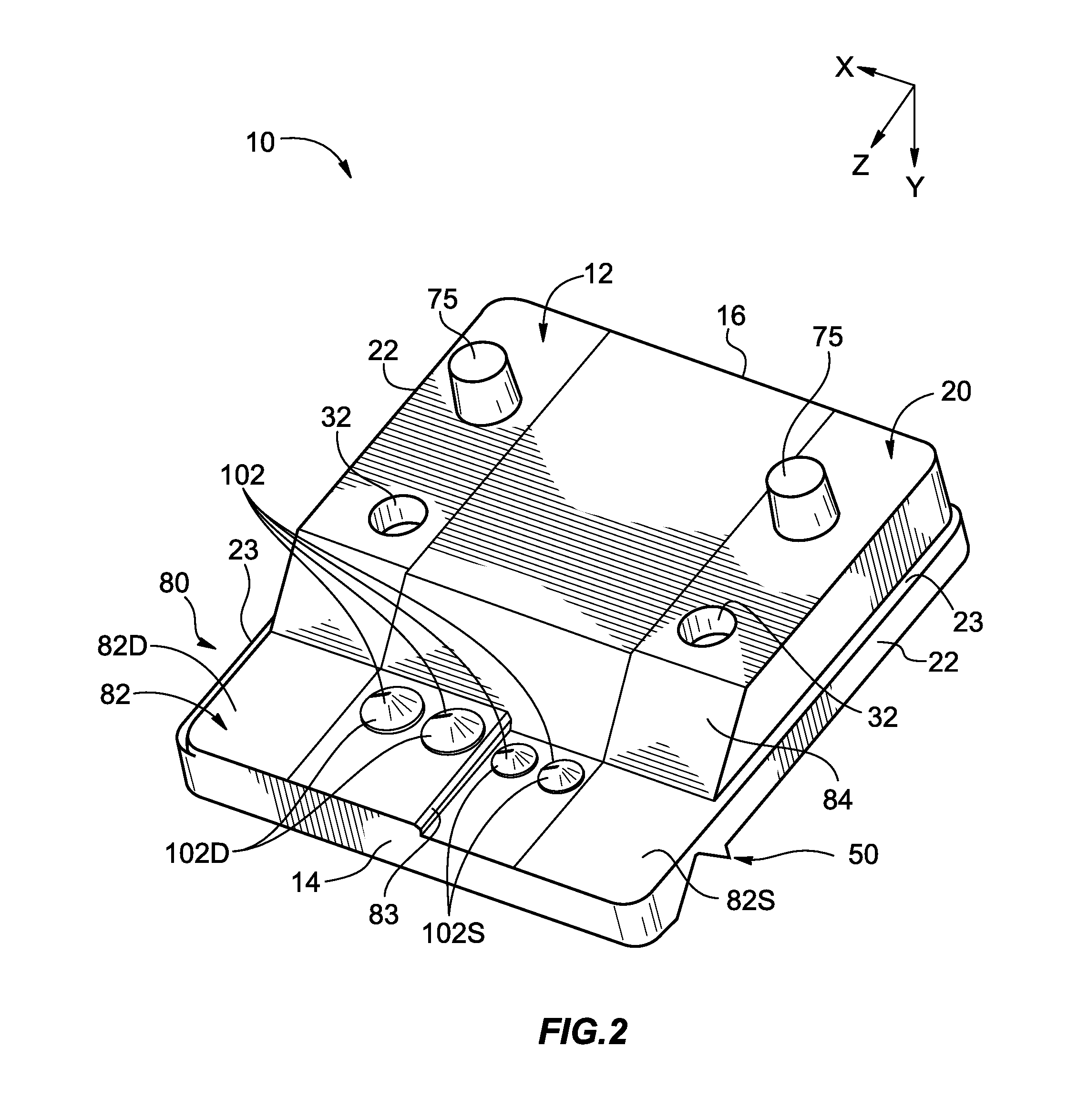
[0070]FIG. 1 is a top-down elevated view of an exemplary fiber optic interface module (hereinafter “module”) 10 according to the disclosure. FIG. 2 is a bottom-up view of the module 10 of FIG. 1, while FIG. 3A and FIG. 3B are cross-sectional views of the example module 10 of FIGS. 1 and 2 as taken ...


PUM


Abstract

Fiber optic interface modules and assemblies using same are disclosed, wherein the module includes first and second lenses formed therein that utilize total-internal reflection within the module body. The first and second lenses define first and second optical paths of different lengths. The module may operably support first and second optical fibers so that they are optically coupled to surfaces of the first and second lenses. The first and second lenses are designed to provide predetermined tolerances for lateral offsets relative to first and second active photo-devices while maintaining respective first and second coupling efficiencies between the active photo-devices and the corresponding first and second optical fibers.

Description

CROSS-REFERENCE TO RELATED APPLICATIONS[0001]This application is related to U.S. patent application Ser. No. ______, entitled “Total-internal-reflection fiber optic interface modules and assemblies,” and to U.S. patent application Ser. No. ______, entitled “Misalignment-tolerant total-internal-reflection fiber optic interface modules and assemblies with high coupling efficiency,” filed on even date herewith, and which are incorporated by reference in their entirety herein.FIELD[0002]The present disclosure relates to fiber optic interface modules and assemblies using the modules, and in particular to such modules and assemblies wherein the module employs total internal reflection and has different optical paths for transmit and receive channels that are respectively associated with active photo-devices such as a light source and a photodetector.BACKGROUND ART[0003]Short-distance data links used for consumer electronics are reaching increasingly higher data rates, especially those use...

Claims


Application Information

Patent Timeline
Patent Type & Authority Applications(United States)
IPC IPC(8): G02B6/12
CPCG02B6/4214G02B6/4249G02B6/4246G02B6/423G02B6/32
Inventor CHARBONNEAU-LEFORT, MATHIEU
Owner CORNING OPTICAL COMM LLC
Learn More